
|
INFO: FMX to 4R70W |
Post Reply 
|
| Author | ||||||||||||||||||||||||||||||||||||||||||||||||||||||||
peter.jenerette 
Senior Member 

Joined: 08-February-2023 Location: Nevada, TX Status: Offline Points: 1054 |
 Post Options Post Options
") Thanks(1) Thanks(1)
 Quote Reply Quote Reply
 Topic: INFO: FMX to 4R70W Topic: INFO: FMX to 4R70WPosted: 24-March-2025 at 6:35AM |
|||||||||||||||||||||||||||||||||||||||||||||||||||||||
|
After completing my 72 351C-2V FMX I had to replace the chunk, and opted for a 3.50, this in result created much higher highway RPMs than desired. This drove me to look into an AOD or 4R70W swap. After much review I decided to go with the 4R70W due to the state of transmission controllers and other information. I had headaches with an AOD in a Mark VII due to what one would think to be a minor adjustment on the cable.
My adventure with details are in my Project Thread starting on Pg. 10 All my research showed it could be done, but there just wasn't much information on it in a 72 up Torino. I am starting this thread to put together a pretty concise list of what worked for me. For starters, I couldn't find any definitive parts list or list of 'gotchas'. I hope that this post would make it a weekend project for some, as I did this myself over the course of several weeks, a couple hours here and there. I converted from an FMX, some points may be different for C4/C6/Manual conversions to the 4R70W. You can use this post for basics on an AOD swap, but there are differences. Some key points on converting 72, early 73, and late 73 onward to an 4R70W.
Here is a beginners parts list, your adventure may vary, but by no means was it cheap.
Part notes: Most used parts came from a 2004 F150 or used what was with the FMX. Shift Arm: The 2004 F150 Shift arm will hit the tunnel unless modified, I just used the B&M kit, but had to fabricate the attaching pin for the original shift cable. You can opt for an aftermarket Lokar kit. Sensors: I purchased a rebuilt transmission which came without any sensors or exterior fittings, which is why they are in the list. TPS: I was creative in my attaching of the TPS, I will cover that here later, but went through 2 variations of connections to the throttle. That covers the basics, I will add posts to focus on key areas of the conversion. 1. Transmission install 2. Attaching hardware, and part fitment 3. Transmission cooler 4. Wiring 5. Drive shaft |
||||||||||||||||||||||||||||||||||||||||||||||||||||||||
|
Pete Jenerette
1972 Gran Torino (H-Code - 4R70W) 2022 F250 XLT 7.3 2003 Thunderbird |
||||||||||||||||||||||||||||||||||||||||||||||||||||||||
 |
||||||||||||||||||||||||||||||||||||||||||||||||||||||||
|
peter.jenerette
Senior Member
Joined: 08-February-2023 Location: Nevada, TX Status: Offline Points: 1054 |
Post Options
Thanks(1)
Quote Reply
Posted: 24-March-2025 at 8:00AM |
|||||||||||||||||||||||||||||||||||||||||||||||||||||||
|
Transmission and installation:
Summary: A 2003-2004 F150 with a 4.2L V6 Automatic (4R70W) will have the following parts: Transmission, Dipstick tube, Trans cooler, Trans cooler lines, Yoke, fittings, shift cable bracket, block spacer, torque converter cover. Prior to install
If going from FMX:
In my project thread you will find the story, but to keep it short... In my search I came across a deal on a rebuilt 4R70W for a 2003 F150 4.2, the price was so right, I ran with it. 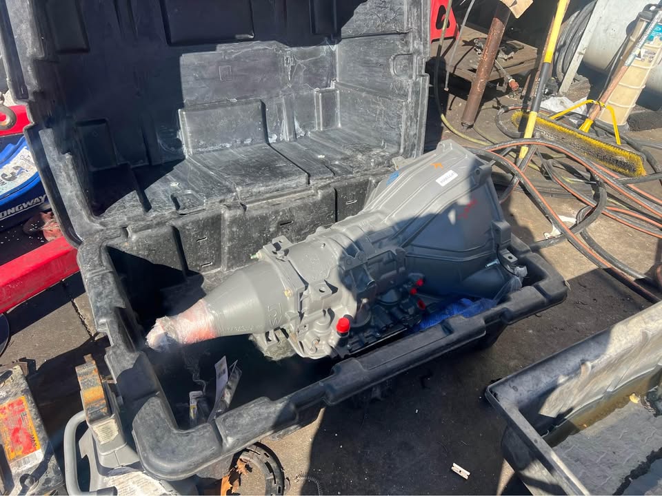 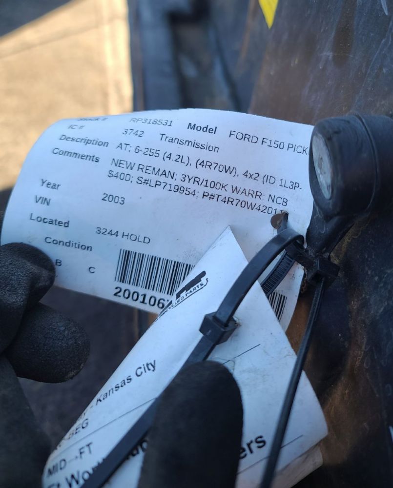 Since this was a new rebuild, it didn't have anything to go with it, including sensors, levers, fittings, etc. Which meant I had to source all of these, If you can find a 2003 or 2004 F150 4.2L V6 you can save a lot of search. Cross member modifications This photo doesn't show all the mods, but it does show the absolute minimum modifications required when not trying to relocate the cross member back further. I ended up removing the lip for the width of the pan as well. The notches are for the pan flange corners on the transmission. Elongating the mount holes gave a bit more wiggle room.  Photo showing the where the dipstick tube is located after installation: 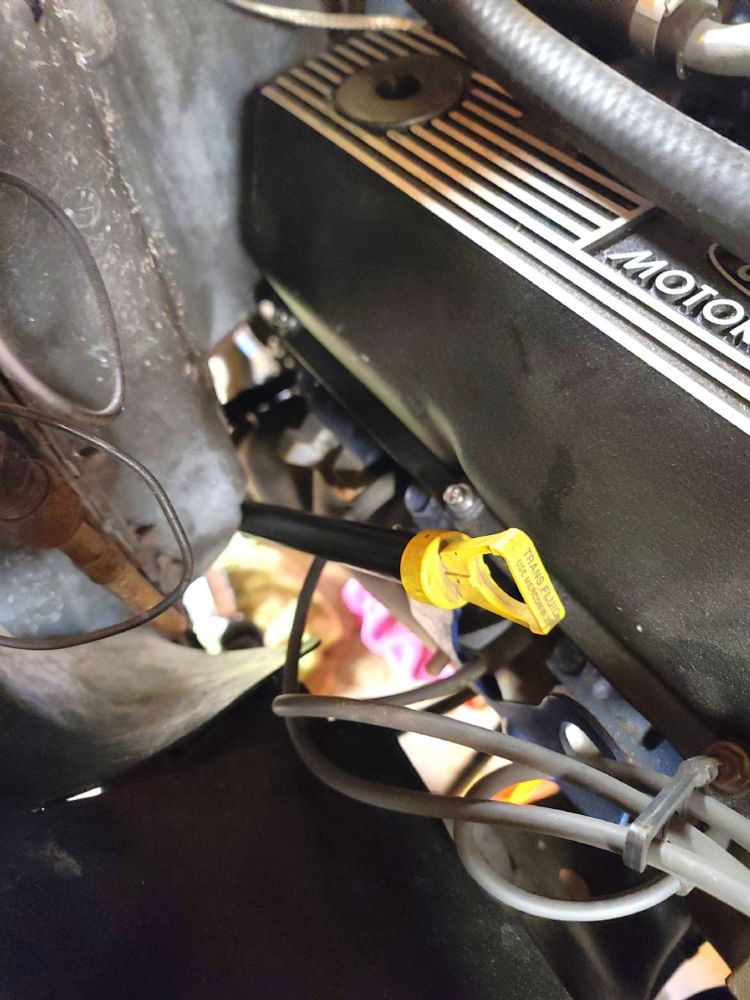 Edited by peter.jenerette - 24-March-2025 at 11:03PM |
||||||||||||||||||||||||||||||||||||||||||||||||||||||||
|
Pete Jenerette
1972 Gran Torino (H-Code - 4R70W) 2022 F250 XLT 7.3 2003 Thunderbird |
||||||||||||||||||||||||||||||||||||||||||||||||||||||||
|
||||||||||||||||||||||||||||||||||||||||||||||||||||||||
|
peter.jenerette
Senior Member
Joined: 08-February-2023 Location: Nevada, TX Status: Offline Points: 1054 |
Post Options
Thanks(1)
Quote Reply
Posted: 24-March-2025 at 8:43AM |
|||||||||||||||||||||||||||||||||||||||||||||||||||||||
|
Throttle Position Sensor (TPS)
The Transmission Control Module (TCM) I used is the Quick2 from US Shift. All will require a throttle position sensor unless you wire it for manual shifting. The basics is find a way to mount a TPS and attach it to your throttle lever, cable or other mechanism. I used a three wire TPS which If I were to do again I would select a different switch with a round provision for a rod vs. the flat tab this one had on it. I had to fabricate my own "rod" mount to the tab. Since I am working with a 2V Cleveland, there are no aftermarket direct bolt ins for this application, if you have a Holley or Edelbrock carb they do make TPS kits for these, if you have an aftermarket TBI, it has a TPS built in. I decided to mount the TPS at the throttle cable mount at the rear of the intake; I fabricated a bracket for the TPS that would attach with the throttle cable retention bolt. 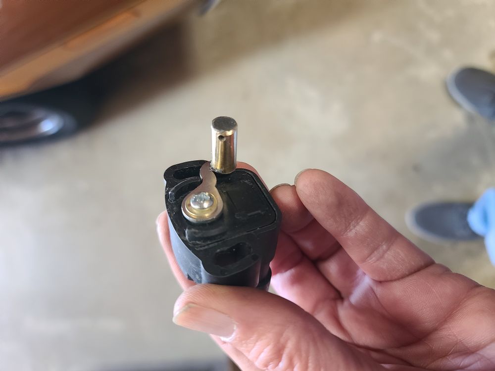 I fabricated a rod that would allow for over run (moving the throttle further than the TPS would move) and connected one end to the original kick down mount location and the other to the TPS. This TPS needs to be almost halfway moved before acceptable voltage is read by the TCM. EDIT: Don't follow this TPS rod placement shown here. Using the Kickdown connection on the linkage drives the TPS at about 5:1, which means at 10% travel the TPS sees 50% throttle. I hope to update with the revised connection and rod, if not in this post look for another later in this thread. Leaving this original part here, although wrong, so others know its been tried... 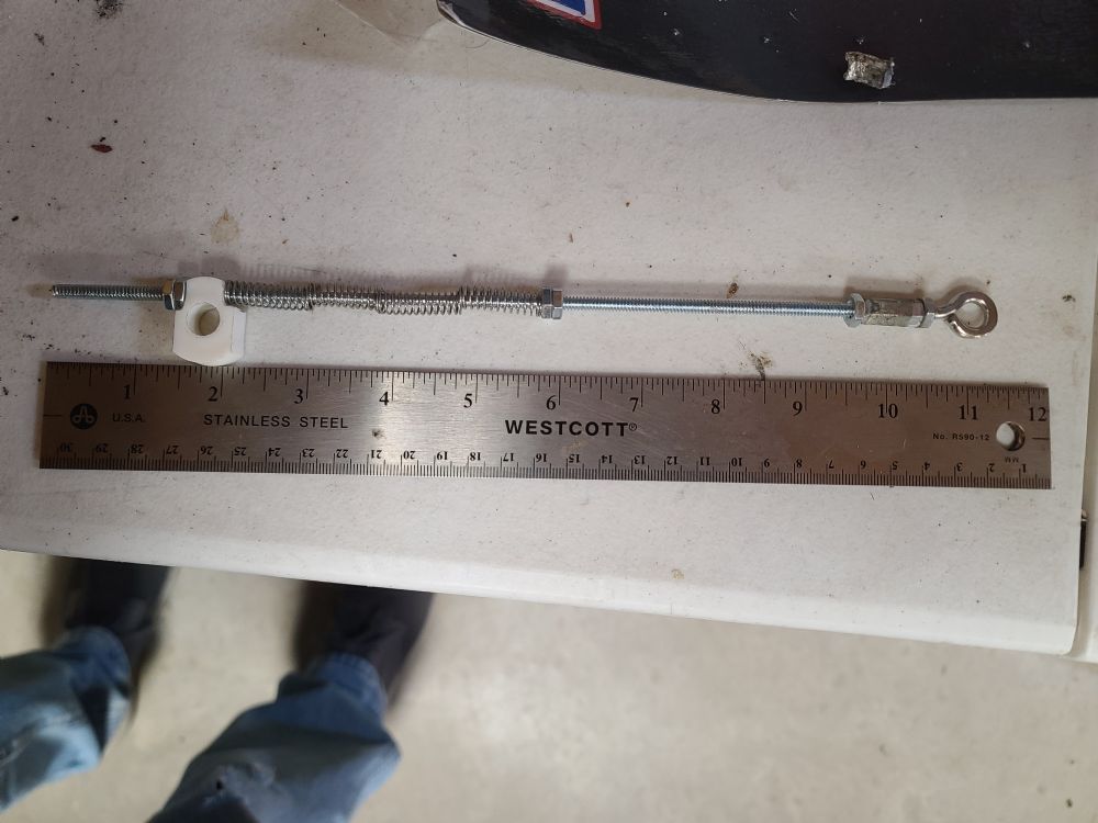 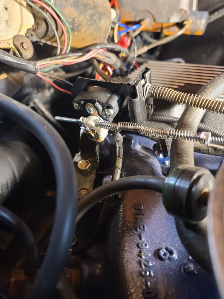 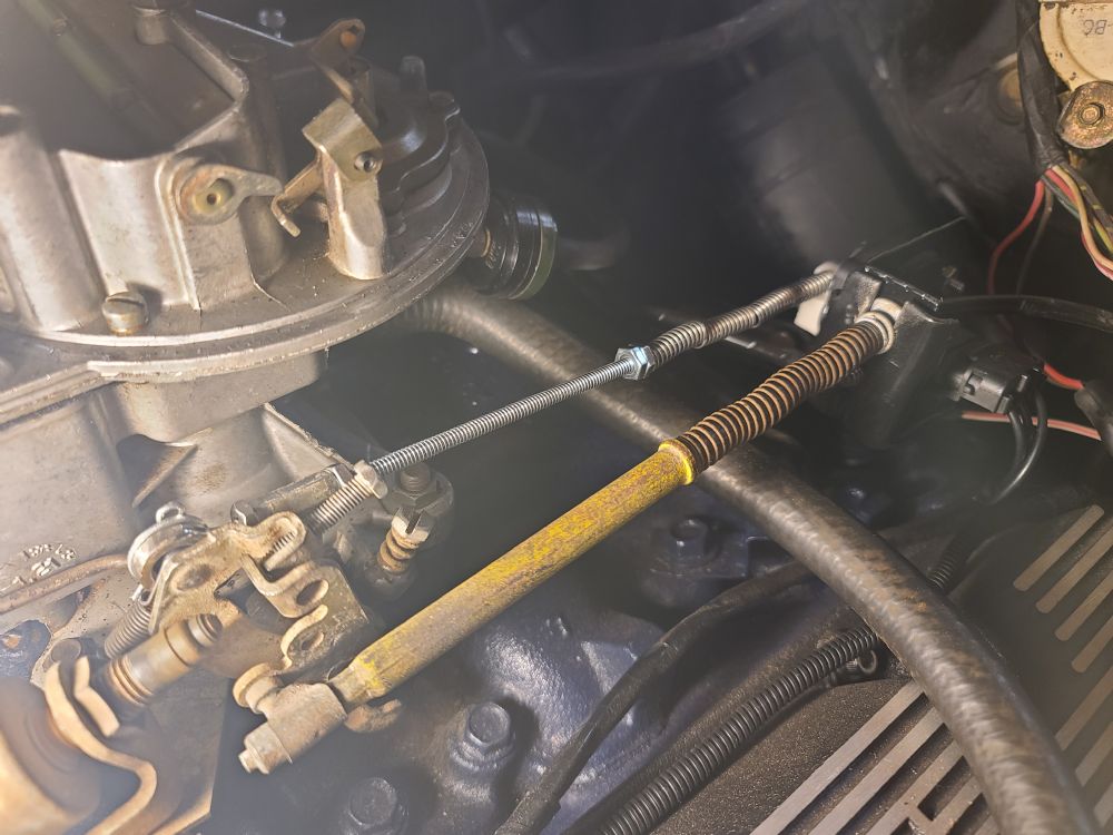 Improved and functional TPS rod As previously stated, the use of the kick down connector generated a 5:1 TPS reading, 10% throttle was showing 50% TPS signal. In this image you can see I simplified the rod with a piece of 1/8" steel rod and connected to a hole in the throttle lever closer to the location of the throttle pull. This gave me a much better ratio and cleaner TPS readings across the board.  Identifying TPS wiring 1. Using an ohm meter set to 10k or 20k, take a reading for each of the three pairs, moving the arm with each reading. The pair where the values do not change while moving the lever are the 5v and ground, the odd one is the SIGNAL wire. 2. Take a reading between the signal wire and each of two identified as ground and 5v, the one with the lowest reading is the Ground wire, the remaining is the +5V wire. Edited by peter.jenerette - 30-March-2025 at 11:21AM |
||||||||||||||||||||||||||||||||||||||||||||||||||||||||
|
Pete Jenerette
1972 Gran Torino (H-Code - 4R70W) 2022 F250 XLT 7.3 2003 Thunderbird |
||||||||||||||||||||||||||||||||||||||||||||||||||||||||
|
||||||||||||||||||||||||||||||||||||||||||||||||||||||||
|
72 RS 351
Senior Member

Joined: 04-September-2014 Location: Knoxville TN Status: Online Points: 3445 |
Post Options
Thanks(0)
Quote Reply
Posted: 24-March-2025 at 9:07AM |
|||||||||||||||||||||||||||||||||||||||||||||||||||||||
|
Most Ford EFI systems use a TPS that has 5v of sweep, and idle is set to be very close to 1.0 volts. I presume the Quick Shift will be looking for that idle voltage, and that the maximum will be under 5v. What you are doing there will be almost the same as what I plan to with my 73 that I'll sell later. So a carb on RPM Air Gap intake, with the Quick Shift for a 4R70W. I have 3.70 and 4.11 gears, most likely OEM LS in both. I hope you like yours with the 3.50 gears, I might leave mine with the 3.70's since I am very used to my three 302 Explorers(4R70W with 3.73's and 29" tires).
|
||||||||||||||||||||||||||||||||||||||||||||||||||||||||
|
Don
73 Ranchero "Sport 72 front end", floor shift/console, planning EFI 7000 rpm 351 stroker 73 Ranchero GT 351C-4V &4R70W for sale later. 92 Lincoln Mark VII SE GTC, OBDII 347/4R70W |
||||||||||||||||||||||||||||||||||||||||||||||||||||||||
|
||||||||||||||||||||||||||||||||||||||||||||||||||||||||
|
peter.jenerette
Senior Member
Joined: 08-February-2023 Location: Nevada, TX Status: Offline Points: 1054 |
Post Options
Thanks(0)
Quote Reply
Posted: 24-March-2025 at 9:13AM |
|||||||||||||||||||||||||||||||||||||||||||||||||||||||
The Quick2 is looking for the 5v; with an idle around 1v, and you are correct, max just below 5. The TPS sensor I have starts at 0, and doesn't hit 1v until about mid sweep. From a gearing perspective, I am quite pleased, from a plug and play perspective, ive got a learning curve to properly set up the Quick2. (Right now I am not keen on the shift points, and every 1-2 shift results in a chirp of the tires.).
|
||||||||||||||||||||||||||||||||||||||||||||||||||||||||
|
Pete Jenerette
1972 Gran Torino (H-Code - 4R70W) 2022 F250 XLT 7.3 2003 Thunderbird |
||||||||||||||||||||||||||||||||||||||||||||||||||||||||
|
||||||||||||||||||||||||||||||||||||||||||||||||||||||||
|
72 RS 351
Senior Member
Joined: 04-September-2014 Location: Knoxville TN Status: Online Points: 3445 |
Post Options
Thanks(0)
Quote Reply
Posted: 24-March-2025 at 11:50AM |
|||||||||||||||||||||||||||||||||||||||||||||||||||||||
|
Hmm, that shifting will take some tuning, I hope. If it is expecting less TPS voltage than what it's seeing, then that tells it that you are harder on the gas than you really are. So hopefully the Quick Shift is commanding more EPC pressure due to the higher TPS voltage, which makes the shifts harder. Dig into it more and find out what it expects the idle TPS to be. My guess was 1.0 volt, which is why I posted it. In OEM EFI the TPS being off affects engine running a lot, rpm hunting etc. But for a separate transmission control system, it might greatly affect the shifting. My plan was to install a nice set of VB parts when I build the trans, and then use the Quick Shift to fine tune the actual shifting, plus the shift points. Try to learn how to control and adjust the trans shifting etc, before even considering altering the valve body etc. It may be some simple adjustments to the TPS or the controller, to dial it in. Keep at it.
 |
||||||||||||||||||||||||||||||||||||||||||||||||||||||||
|
Don
73 Ranchero "Sport 72 front end", floor shift/console, planning EFI 7000 rpm 351 stroker 73 Ranchero GT 351C-4V &4R70W for sale later. 92 Lincoln Mark VII SE GTC, OBDII 347/4R70W |
||||||||||||||||||||||||||||||||||||||||||||||||||||||||
|
||||||||||||||||||||||||||||||||||||||||||||||||||||||||
|
peter.jenerette
Senior Member
Joined: 08-February-2023 Location: Nevada, TX Status: Offline Points: 1054 |
Post Options
Thanks(0)
Quote Reply
Posted: 24-March-2025 at 12:18PM |
|||||||||||||||||||||||||||||||||||||||||||||||||||||||
|
When below 1v at idle, it gives a "TPS Voltage Low" warning. This is how I know the mid-point of my tps is about 1v, since that's where I adjusted it to to remove the warning, at about 1.06 v, the quick2 will tell you it's readings as well as its settings.
You can adjust shift RPMs as well as the shift hardness with the knob, but I'm yet to find the right settings.
|
||||||||||||||||||||||||||||||||||||||||||||||||||||||||
|
Pete Jenerette
1972 Gran Torino (H-Code - 4R70W) 2022 F250 XLT 7.3 2003 Thunderbird |
||||||||||||||||||||||||||||||||||||||||||||||||||||||||
|
||||||||||||||||||||||||||||||||||||||||||||||||||||||||
|
72FordGTS
Admin Group 
GTS.org Admin Joined: 06-September-2005 Location: Ontario, Canada Status: Offline Points: 6780 |
Post Options
Thanks(1)
Quote Reply
Posted: 24-March-2025 at 2:20PM |
|||||||||||||||||||||||||||||||||||||||||||||||||||||||
|
This is an outstanding post Peter. Thank you for taking the time to put this together.
|
||||||||||||||||||||||||||||||||||||||||||||||||||||||||
|
Vince
1972 Ford GTS Sportsroof - Survivor, One Family car GTS.org Admin |
||||||||||||||||||||||||||||||||||||||||||||||||||||||||
|
||||||||||||||||||||||||||||||||||||||||||||||||||||||||
|
peter.jenerette
Senior Member
Joined: 08-February-2023 Location: Nevada, TX Status: Offline Points: 1054 |
Post Options
Thanks(1)
Quote Reply
Posted: 24-March-2025 at 11:00PM |
|||||||||||||||||||||||||||||||||||||||||||||||||||||||
|
Transmission Cooler
I used the transmission cooler and lines from the 2004 F150 4.2 with very little modification. I am not sure that the hard line to cooler was correct for the F150 as it was 3/8 hose from hard line to cooler when I got it.  I cleaned and flushed the parts and mounted the cooler using these aftermarket plastic zip tie type to the AC condenser with the fittings on the passenger side. The very ends of the hard lines come facing straight just past the front of the engine when installed, nicely; I bent about 6 inches of the ends about 45 degrees towards the passenger side to give the hose a more natural route to the cooler. The hoses were then routed through the hole in the radiator support where the AC condenser line passes, then up to and onto the cooler.  |
||||||||||||||||||||||||||||||||||||||||||||||||||||||||
|
Pete Jenerette
1972 Gran Torino (H-Code - 4R70W) 2022 F250 XLT 7.3 2003 Thunderbird |
||||||||||||||||||||||||||||||||||||||||||||||||||||||||
|
||||||||||||||||||||||||||||||||||||||||||||||||||||||||
|
peter.jenerette
Senior Member
Joined: 08-February-2023 Location: Nevada, TX Status: Offline Points: 1054 |
Post Options
Thanks(1)
Quote Reply
Posted: 25-March-2025 at 1:47AM |
|||||||||||||||||||||||||||||||||||||||||||||||||||||||
|
Wiring
For the wiring, the Quick2 comes with a great harness, nicely labelled wires, and plenty of length. There won't be many photos, but this should give anyone a good idea. The harnesses for the Quick2 come prewired for your specific transmission with the appropriate connectors. It's one harness per connection. Prior to installing the transmission, I made my general wire routing and tap decisions. You will definitely need
Those basic four connections will make it operational. For routing, I connected all the connectors at the transmission and bundled them towards the bell housing and up. I had previously pulled the dash pad and gauge facia to remove the speedometer cable completely, and routed the harness through the speedometer hole, of course acquiring a new grommet. I mounted my controller in the un-equiped clock location, see my project thread for this. Connections
I also routed wires for the Dakota Digital speedometer drive and connected that all up, but at the time of this writing, I am yet to set it up or test it. That will be in a future post. |
||||||||||||||||||||||||||||||||||||||||||||||||||||||||
|
Pete Jenerette
1972 Gran Torino (H-Code - 4R70W) 2022 F250 XLT 7.3 2003 Thunderbird |
||||||||||||||||||||||||||||||||||||||||||||||||||||||||
|
||||||||||||||||||||||||||||||||||||||||||||||||||||||||
|
peter.jenerette
Senior Member
Joined: 08-February-2023 Location: Nevada, TX Status: Offline Points: 1054 |
Post Options
Thanks(0)
Quote Reply
Posted: 25-March-2025 at 11:59PM |
|||||||||||||||||||||||||||||||||||||||||||||||||||||||
I need to go and check my TPS set up; I couldn't get the "TPS Voltage low" message to clear until I had Idle at almost 1.0v; but the documentation says the minimum is 0.2v. That is alot of throttle sweep I am missing on the TPS. Will go check that again next opportunity.
|
||||||||||||||||||||||||||||||||||||||||||||||||||||||||
|
Pete Jenerette
1972 Gran Torino (H-Code - 4R70W) 2022 F250 XLT 7.3 2003 Thunderbird |
||||||||||||||||||||||||||||||||||||||||||||||||||||||||
|
||||||||||||||||||||||||||||||||||||||||||||||||||||||||
|
72 RS 351
Senior Member
Joined: 04-September-2014 Location: Knoxville TN Status: Online Points: 3445 |
Post Options
Thanks(0)
Quote Reply
Posted: 26-March-2025 at 12:25AM |
|||||||||||||||||||||||||||||||||||||||||||||||||||||||
|
I hope they have very good instructions with the detailed specs, the voltage sweep needed from the TPS. That's why I mentioned it, the Ford EFI since the first in 1985ish always used 1.0 volts at idle. The early EFI required that voltage, if it was off that hurt everything. The next version of computers started setting the idle voltage benchmark at whatever the TPS showed at each start up. That is much better and slight variations didn't hurt much at all. But the idle TPS has always been right at 1.0 volt ideally, and it should never be below that. Typically 4.5v is the high side that most people have ever measured. So look at the TPS voltage sweep as 1.0-4.5 volts ideally, make it close with idle at 1.0v, and I bet it should be fine.
|
||||||||||||||||||||||||||||||||||||||||||||||||||||||||
|
Don
73 Ranchero "Sport 72 front end", floor shift/console, planning EFI 7000 rpm 351 stroker 73 Ranchero GT 351C-4V &4R70W for sale later. 92 Lincoln Mark VII SE GTC, OBDII 347/4R70W |
||||||||||||||||||||||||||||||||||||||||||||||||||||||||
|
||||||||||||||||||||||||||||||||||||||||||||||||||||||||
|
peter.jenerette
Senior Member
Joined: 08-February-2023 Location: Nevada, TX Status: Offline Points: 1054 |
Post Options
Thanks(0)
Quote Reply
Posted: 30-March-2025 at 12:47AM |
|||||||||||||||||||||||||||||||||||||||||||||||||||||||
|
Figured out the consistent bark in the 1-2 shift.
(I will update my TPS post when i get a pic for it.) Using the kickdown lever position on the throttle was my issue, the distance from throttle plate center to the connection point was driving the TPS at about 5 to 1, so, 10% travel on the throttle was giving 50% travel on the TPS. I moved the connection about 1" closer towards the butteryfly center line, and voila, normal shifting, that i can now adjust.
|
||||||||||||||||||||||||||||||||||||||||||||||||||||||||
|
Pete Jenerette
1972 Gran Torino (H-Code - 4R70W) 2022 F250 XLT 7.3 2003 Thunderbird |
||||||||||||||||||||||||||||||||||||||||||||||||||||||||
|
||||||||||||||||||||||||||||||||||||||||||||||||||||||||
|
72 RS 351
Senior Member
Joined: 04-September-2014 Location: Knoxville TN Status: Online Points: 3445 |
Post Options
Thanks(0)
Quote Reply
Posted: 30-March-2025 at 6:38AM |
|||||||||||||||||||||||||||||||||||||||||||||||||||||||
|
Good update, little tweaks make a difference. I installed a Lokar AOD cable once to a normal Holley carb. It did work but it took a lot of time to get it connected and moving right. I'd rather not have to do that again.
|
||||||||||||||||||||||||||||||||||||||||||||||||||||||||
|
Don
73 Ranchero "Sport 72 front end", floor shift/console, planning EFI 7000 rpm 351 stroker 73 Ranchero GT 351C-4V &4R70W for sale later. 92 Lincoln Mark VII SE GTC, OBDII 347/4R70W |
||||||||||||||||||||||||||||||||||||||||||||||||||||||||
|
||||||||||||||||||||||||||||||||||||||||||||||||||||||||
|
peter.jenerette
Senior Member
Joined: 08-February-2023 Location: Nevada, TX Status: Offline Points: 1054 |
Post Options
Thanks(1)
Quote Reply
Posted: 30-March-2025 at 11:56AM |
|||||||||||||||||||||||||||||||||||||||||||||||||||||||
|
Driveshaft
If you go with an AOD, the length of the transmission is the same as an FMX, and you CAN use your driveshaft as is. The AOD will accept the yoke from a C4 or a top loader. The 4R70W is 1" or so longer than an FMX, you cannot use a yoke from a C4 or top loader as the 4R70W yoke diameter is 0.1 inches wider, so the other yoke won't seal. The 4R70W will require you get your driveshaft shortened by about 1.0", Do your u-joint homework using a pair of calipers, rear u-joint will be same as always, but depending on your yoke selection, you may need a hybrid. Shortened original 72 FMX driveshaft (clean one) next to original 72 FMX driveshaft. 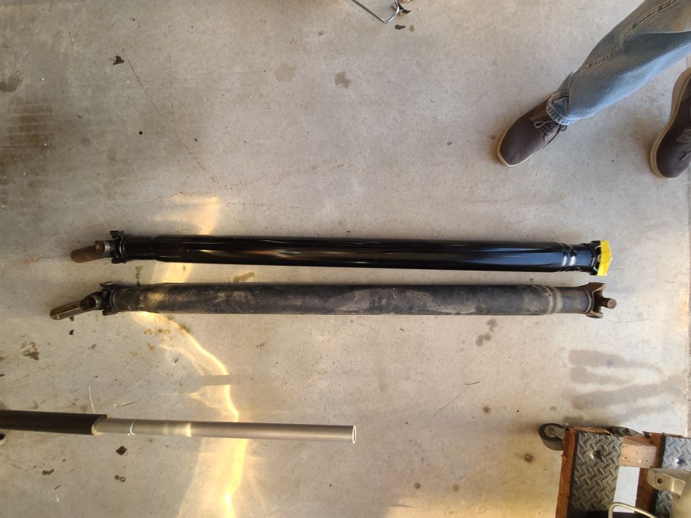 |
||||||||||||||||||||||||||||||||||||||||||||||||||||||||
|
Pete Jenerette
1972 Gran Torino (H-Code - 4R70W) 2022 F250 XLT 7.3 2003 Thunderbird |
||||||||||||||||||||||||||||||||||||||||||||||||||||||||
|
||||||||||||||||||||||||||||||||||||||||||||||||||||||||
|
peter.jenerette
Senior Member
Joined: 08-February-2023 Location: Nevada, TX Status: Offline Points: 1054 |
Post Options
Thanks(1)
Quote Reply
Posted: 28-April-2025 at 4:27AM |
|||||||||||||||||||||||||||||||||||||||||||||||||||||||
|
Dakota Digital ECD200-BT Electronic Speedometer Cable Drive.
Since my 4R70W did not have a gear on the output shaft for a mechanical speedometer I needed to find my options, there are a few out there (listed in my build thread). I chose the Dakota Digital ECD200-BT. Wiring is pretty simple, tan wire from the Quick2 for the speedometer input, power and a couple of grounds. Hard part was finding a place to mount it without binding the provided cable. A 12 inch cable would have been much better. With the provided cable, I have it mounted under the carpet between the fuse box steering column. Configuring Reading the instructions makes it seem like a pain, and there is no information on the app that i could find, but here's how it went. (I should have just done this when I first set up the trans). After setting it up, the speedo now reads within 5% of the digital speedometer read out on the USShift Quick2, which calculates its speed based on rear diff and tire size settings against the OSS. You need to have a known measured mile, I located five 1 mile sections of an 8 mile drive using my F250 before I actually set it up. I know the following will be short, but without documentation I wasn't sure how to do this.
*NOTE: You may need to make sure the Speedo out is set up on the Quick2 or TCM. That's it. After the first mile and completing the Auto Calibration, I drove the rest of the trip at a variety of speeds and checked the distance on the odometer for each mile, it was quite close. Overall, I am quite pleased with this gadget and it giving me the ability to retain the original speedo. 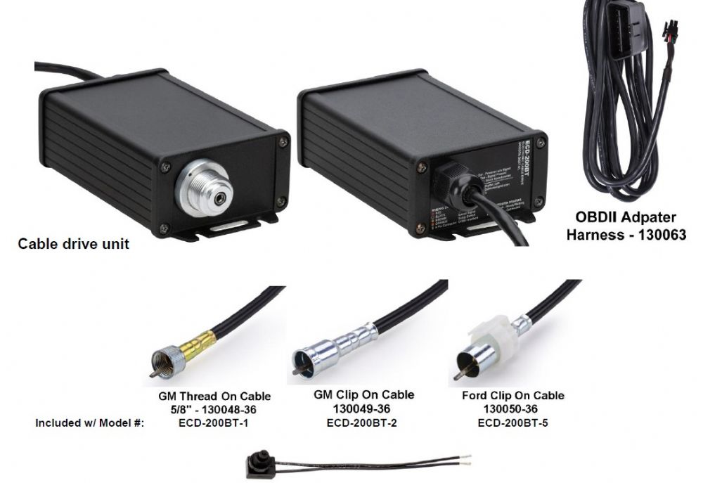 Edited by peter.jenerette - 28-April-2025 at 4:39AM |
||||||||||||||||||||||||||||||||||||||||||||||||||||||||
|
Pete Jenerette
1972 Gran Torino (H-Code - 4R70W) 2022 F250 XLT 7.3 2003 Thunderbird |
||||||||||||||||||||||||||||||||||||||||||||||||||||||||
|
||||||||||||||||||||||||||||||||||||||||||||||||||||||||
|
peter.jenerette
Senior Member
Joined: 08-February-2023 Location: Nevada, TX Status: Offline Points: 1054 |
Post Options
Thanks(0)
Quote Reply
Posted: 25-May-2025 at 2:08PM |
|||||||||||||||||||||||||||||||||||||||||||||||||||||||
|
TPS UPDATE I revisited the TPS adjustment since I built a better rod to drive it, and set it to 0.68v at idle, this gives me a little more throw on the TPS and the car now seems much smoother, especially on light acceleration. Quick 2 manual says idle TPS can not be below 0.38, I may try to get a couple more tenths out of it in the future. |
||||||||||||||||||||||||||||||||||||||||||||||||||||||||
|
Pete Jenerette
1972 Gran Torino (H-Code - 4R70W) 2022 F250 XLT 7.3 2003 Thunderbird |
||||||||||||||||||||||||||||||||||||||||||||||||||||||||
|
||||||||||||||||||||||||||||||||||||||||||||||||||||||||
|
peter.jenerette
Senior Member
Joined: 08-February-2023 Location: Nevada, TX Status: Offline Points: 1054 |
Post Options
Thanks(0)
Quote Reply
Posted: 02-June-2025 at 1:45AM |
|||||||||||||||||||||||||||||||||||||||||||||||||||||||
|
QUICK 2 UPDATE
After a few stints, I was getting an error on the Quick2 when I crossed 70 mph, "Error Ratio Too High for Gear 4". I figured one of two things was causing it. 1. Tach feed was not accurate. 2. Output shaft speed sensor was giving odd readings at speed. Google wouldn't give me any clues, so...I emailed USShift and asked, giving them my set up: Their response:
Needless to say this did resolve the Error, but I still have the speedo issue over 70, I may swap out the OSS to a name brand one to see if that alleviates that issue. |
||||||||||||||||||||||||||||||||||||||||||||||||||||||||
|
Pete Jenerette
1972 Gran Torino (H-Code - 4R70W) 2022 F250 XLT 7.3 2003 Thunderbird |
||||||||||||||||||||||||||||||||||||||||||||||||||||||||
|
||||||||||||||||||||||||||||||||||||||||||||||||||||||||
|
peter.jenerette
Senior Member
Joined: 08-February-2023 Location: Nevada, TX Status: Offline Points: 1054 |
Post Options
Thanks(0)
Quote Reply
Posted: 15-July-2025 at 6:17AM |
|||||||||||||||||||||||||||||||||||||||||||||||||||||||
|
Quick update; Attempting to get my AC working, I ran into a heat soak issue, which I am still trying to figure out. During this I noted that I had the Transmission cooler less than 0.75 inches from the condenser so i relocated it.
I had a couple of lower brackets from the new condenser and mounted the trans cooler about 3 inches away; don't know that it will help but i think it looks better. 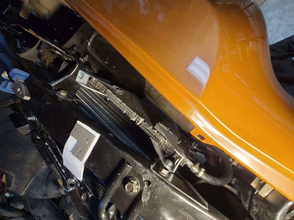 That's all. :-)
|
||||||||||||||||||||||||||||||||||||||||||||||||||||||||
|
Pete Jenerette
1972 Gran Torino (H-Code - 4R70W) 2022 F250 XLT 7.3 2003 Thunderbird |
||||||||||||||||||||||||||||||||||||||||||||||||||||||||
|
||||||||||||||||||||||||||||||||||||||||||||||||||||||||
|
72 RS 351
Senior Member
Joined: 04-September-2014 Location: Knoxville TN Status: Online Points: 3445 |
Post Options
Thanks(0)
Quote Reply
Posted: 15-July-2025 at 6:55AM |
|||||||||||||||||||||||||||||||||||||||||||||||||||||||
|
Try to keep the obstacles away from the condenser's outlet area, which I think is near the top usually. The condenser should see the best clean airflow. What condenser do you have in the car, what is the most popular for an R-134 system in these 70's cars? Plus did you spend long hunting for those? I haven't started on mine yet, but that might be one of my first items to hunt, to reinstall AC in my truck.
|
||||||||||||||||||||||||||||||||||||||||||||||||||||||||
|
Don
73 Ranchero "Sport 72 front end", floor shift/console, planning EFI 7000 rpm 351 stroker 73 Ranchero GT 351C-4V &4R70W for sale later. 92 Lincoln Mark VII SE GTC, OBDII 347/4R70W |
||||||||||||||||||||||||||||||||||||||||||||||||||||||||
|
||||||||||||||||||||||||||||||||||||||||||||||||||||||||
|
peter.jenerette
Senior Member
Joined: 08-February-2023 Location: Nevada, TX Status: Offline Points: 1054 |
Post Options
Thanks(0)
Quote Reply
Posted: 15-July-2025 at 11:24AM |
|||||||||||||||||||||||||||||||||||||||||||||||||||||||
I went with the factory standard R134 approved condenser; I probably should have opted for a parallel flow which is better for 134A. Most popular upgrades are to go with the Sanden compressor, Parallel flow condenser, new TEV, and POV. @Eliteman - has had some experience with conversions, and I believe he is currently in a love/hate relationship with his system. Im using a 134A approved York, with the above condenser, I get decent AC out of it, not R12 decent, but what i think is acceptable (based on my limited drive time). I have to deal with the current heat soak issue, which may or may not be related to the AC implementation.
|
||||||||||||||||||||||||||||||||||||||||||||||||||||||||
|
Pete Jenerette
1972 Gran Torino (H-Code - 4R70W) 2022 F250 XLT 7.3 2003 Thunderbird |
||||||||||||||||||||||||||||||||||||||||||||||||||||||||
|
||||||||||||||||||||||||||||||||||||||||||||||||||||||||
|
72 RS 351
Senior Member
Joined: 04-September-2014 Location: Knoxville TN Status: Online Points: 3445 |
Post Options
Thanks(0)
Quote Reply
Posted: 15-July-2025 at 12:58PM |
|||||||||||||||||||||||||||||||||||||||||||||||||||||||
|
Keep working at it, you have most of your car project done it seems to me. The little steps to finish it should be less overwhelming than the early steps were. I'd watch the fluid temps closely, the coolant and ATF affect the AC more than the oil for instance. Have good airflow through the grille and condenser, install air walls to funnel air completely through the condenser and radiator. The AC systems I've never messed with much other than replacing o-rings and other parts, plus using an AC shop to fill etc. I'll see how lucky or not I am soon when I try to adapt a 1996-2001 302 Explorer front dress to my 351C. I hope to use that AC compressor along with the PS pump etc. If it'll work, then those parts will be easier to come by in the future.
|
||||||||||||||||||||||||||||||||||||||||||||||||||||||||
|
Don
73 Ranchero "Sport 72 front end", floor shift/console, planning EFI 7000 rpm 351 stroker 73 Ranchero GT 351C-4V &4R70W for sale later. 92 Lincoln Mark VII SE GTC, OBDII 347/4R70W |
||||||||||||||||||||||||||||||||||||||||||||||||||||||||
|
||||||||||||||||||||||||||||||||||||||||||||||||||||||||
|
Post Reply
|
|
| Tweet |
| Forum Jump | Forum Permissions You cannot post new topics in this forum You cannot reply to topics in this forum You cannot delete your posts in this forum You cannot edit your posts in this forum You cannot create polls in this forum You cannot vote in polls in this forum |


 Topic Options
 72 RS 351 wrote: