Reading the Electrical Schematic
Printed From: The Ford Torino Page
Category: Model Specific Forum
Forum Name: General Automotive Technical Discussion
Forum Description: Technical Automotive discussion of anything not specific to mid-size Ford/Merc
URL: https://forum.grantorinosport.org/forum_posts.asp?TID=18750
Printed Date: 19-April-2024 at 6:59PM
Software Version: Web Wiz Forums 12.06 - https://www.webwizforums.com
Topic: Reading the Electrical Schematic
Posted By: squarethumps
Subject: Reading the Electrical Schematic
Date Posted: 10-April-2020 at 7:31AM
Hi All, I was wondering if someone might know what these numbers (16, 20, 8, 298, 181, 687, 54 .. etc ) are prior to the wire color designation on this electrical schematic I have. It seems to be a rather official type schematic.  I can pretty much follow it with the wires / connectors / peripherals, I'm just wondering if those numbers have significance. I seem to be missing the cover of this group of schematic drawings, if it ever had one, but I have the index. I'm trying to sort out why I have power to that one coil wire on the engine side of the firewall when starting the car, but not when the key is in the "Run" position. I thought I identified the one place on top of the switch that has power in both the Run and the Start positions, but where the two wires connect at the firewall to the one coil wire on the other side only gets power in the Start position. I'm trying to really understand the purpose of all the wires and want to make sure that all the gauges work and neutral switches and everything. It's all there, just something isn't working. Thanks. |
Replies:
Posted By: aquartlow
Date Posted: 10-April-2020 at 8:56AM
|
"Start" uses full 12V(or full battery power) whereas "Run" is passed through a resistance wire which reduces voltage to approx. between 8-9 volts. Not sure how you are testing(12V test light or VOM meter), a test light may not show the wire in "Run" position even having voltage(they usually will just with reduced bulb brightness) or you may have an internal issue with the ignition switch and/or ignition switch plug's wiring. ------------- www.supermotors.net/22468 Yeah, It's a Hybrid...It burns gas and tires. No matter how good she looks, somebody, somewhere, is tired of her sh*t. Beauty is skin deep, ugliness goes clear to the bone. |
Posted By: squarethumps
Date Posted: 10-April-2020 at 10:59AM
|
ok yes, I understand the difference in the wires resistance. See I thought I had been through all of this before and got it sorted out. There is an MSD distributor and coil and I could get the car running but it would always putter out slowly and I couldn't get it running _good_. It would run but it sounded like it was missing. When I put 12 volts from the battery to the coil everything worked fine. So I started digging and using the ohm test I figured out that the wire was resisting the voltage and causing the MSD to not get the 12 V it needs, thus causing the coil to charge slower. So I bought and installed a step-up voltage directly before the coil and thought all it was done. That was about a year ago. Now I finally ( thanks covid ) am back working on it, and it's not working in the run position. So now I'm back tracking down every wire and re-learning everything I thought I knew, but clearly don't. Using the schematic I thought I could figure out why I'm not getting the power through the resistance wire, but at the moment I'm not exactly sure which wire it is. I'm trying to identify which post(s) out of the ignition switch carry current when in the start and the run position, and I thought that they both started from the same post at that switch, and then ended up at the same post at junction block behind the fuse box, however, the one of the wires was part of some additional switches / circuits ( the neutral switch maybe ? tach ? I'm just not sure how all that is put together ). It's all there in the schematic, I believe, but I'm having some trouble understanding it, and what is ok that is missing or what should be added given the fact that the ignition control module ( ignition box ? ) is removed from the system. I'm guessing that it is internal to the MSD distributor now ? Not sure. Much to sort out and learn. Any and all advice is appreciated. |
Posted By: californiajohnny
Date Posted: 10-April-2020 at 1:39PM
|
not sure on that schematic but i've seen numbered designations before on multi page schematics that designate a connector listed in the schematic as it may not show on a different page if that makes sense? may not be the case here??? ------------- JOHN 74 GRAN TORINO S&H CLONE 74 VETTE CUSTOM 90 S10 BLAZER 4X4 LIFTED 77 CELICA CUSTOM 75 V8 MONZA SUPERCHARGED 79 COURIER VERT. SLAMMED 75 VEGA V6 5 SPD 70 CHEV C10 P/U 68 MUSTANG FB CONVERSION |
Posted By: TV 2M8O
Date Posted: 11-April-2020 at 7:16AM
In your first photo, the "14401", "14398" designate that particular harness part number. In your second photo, the 16, 20, 8, 298, 181, 687, 54 .. etc designate the circuit number. Think of them as the route numbers on a road map so when you go to the next page, you'll know what "route" number to look for. The schematics are really just a map of the individual circuits in our cars. Also the LB-R, LB-Y, GY-Y, W-LB H, P-O H designate the wire color and designator. LB-R is Light Blue with Red stripe, GY-Y is Gray wire with Yellow stripe, P-O H is Purple with Orange Hash stripe. Hope this helps!! -------------  TV 2M8O OUT JOE 1976 Gran Torino S&H season 2-4 Clone Project Blog: http://tv2m8o.blogspot.com/ |
 squarethumps wrote:
Posted By: squarethumps
Date Posted: 11-April-2020 at 9:34AM
|
For some reason I can not find the "quote" function on here but : <quote>16, 20, 8, 298, 181, 687, 54 .. etc designate the circuit number. Think of them as the route numbers on a road map so when you go to the next page, you'll know what "route" number to look for.</quote> This is excellent information, thank you so much for the detailed explanation. Also -- knowing that the 14398 corresponds to the harness part number !!! Had no idea that was listed on these sheets. I guess they were worth the money I paid ( which truthfully wasn't too much ). I've now found brand new OEM parts on ebay for these. Fantastic thank you !! Hopefully I should be able to sort out the wiring under the dash. Once I understand what is currently there, I guess the next challenge is to understand the effects are of having the ignition module box removed, and replaced by the MSD distributor.   The following pictures taken from the "Power Distribution" page has the ignition switch, and in that same image one can see the C-801. Assuming C stands for Connect(or/ion), it matches the other image of the pins on the connectors that are there. The Switch Position diagram I'm a little unsure of also. It seems to show, in the middle that when there is power flowing because the key switch is in the "Start" position, that power is flowing out of the switch, through the 32 R-LB wire route, (though I'm not sure what's going on with the 297 BK-LG H route at that moment) and when it is in the Run position, the power is flowing out of 2 wires, split starting immediately at the connector : the 16 R-LG circuit and another one ( It is the 20 W-LB H, not in the above jpeg ) That 16R-LG splits again at the S-801 ( S stands for Splice I believe ), and the 16R-LG actually goes to the a fuse ... and on it goes ). The point being is that the there are in fact 2 different posts (if I'm reading that correctly) that the + voltage travels to get to the coil depending on which position the key switch is in, and that is the first place to start the diagnosis. I should be get +12v on each but not at the same time. If that is working then the next step is tracking down the 16 and the 20 "routes" I guess to see what's missing. Thanks again for any and all advice. |
Posted By: TV 2M8O
Date Posted: 12-April-2020 at 5:38AM
|
The "QUOTE" feature should be in the header bar of the comment you want to quote.... ------------- TV 2M8O OUT JOE 1976 Gran Torino S&H season 2-4 Clone Project Blog: http://tv2m8o.blogspot.com/ |
Posted By: squarethumps
Date Posted: 13-April-2020 at 2:52AM
Thanks. |
Posted By: squarethumps
Date Posted: 08-May-2020 at 6:35AM
|
Hi All, A success update here and the introduction of the next issue. If you examine the picture I posted where you see the IGNITION SWITCH and SWITCH POSITION diagram, you can see a splice S-801 on the 16 - R - LG circuit. It is this splice that was disconnected. The description of the splice in the document says that it is over by the heater box, and, indeed it is. The resistor wire was simply disconnected from the other two wires. I don't really understand why the splice is way over there kind of on the other side of the car, but that's where the wires all terminate, and that's where they (should have been) all joined together. A wire nut solved this issue, and now the proper resistor wire is carrying the voltage to the firewall block, and then on to the MSD voltage hop-up I have so that the MSD coil and distributor is receiving the correct amount of voltage and it is working. The next concerning thing is to figure out why it is working because the tachometer is NOT hooked up! If you look at the diagram in this thread : http://forum.grantorinosport.org/info-72-79-gauge-clusters-and-wiring_topic2933.html" rel="nofollow - http://forum.grantorinosport.org/info-72-79-gauge-clusters-and-wiring_topic2933.html The tachometer should be hooked to that coil wire on the engine side of the firewall. If the tach isn't hooked up, the circuit should not be complete and no power should be getting to the coil. I need to figure out what happened to those original splices where the tach should be connected. My intention is to find where that should be on the engine side of the firewall and then make sure the tach is working. This splice would be BEFORE my MSD votage hop-up, of course. I may be posting a whole other thread on this topic, because, again if you look at the above thread, the picture of the 74-76 wiring at the back of the tach, which is also part of the little bundle that includes the ammeter and the clock, I can't find where those wires all connect to. It seems as though the entire 6 pin connector is missing. The back of my instrument cluster has all the barrel pins for the tach, clock, and ammeter, but the actual grey connector just isn't there, and I can't seem to locate it under the dash. Quite odd. That actual connector I am referring to is NOT pictured in that wiring picture I mention. In that picture, all 6 wires just disappear off to the left. It would be nice to see that connector, though with the schematic I have I pretty much know what it looks like. It is labeled as connector C-209. |
Posted By: 72FordGTS
Date Posted: 08-May-2020 at 12:32PM
|
I am not really sure what you are asking about the tach? However, you are right, the tach needs to be connected to complete the circuit to the coil. However, you can get around this by converting your tach to a voltage sensing tach. That's what I did so I could run a full 12 volts to the coil and not worry about frying the tach (which needs the resistor wire). Rocketman converted my tach - top notch work. http://www.rccinnovations.com/index.php" rel="nofollow - http://www.rccinnovations.com/index.php ------------- Vince 1972 Ford GTS Sportsroof - Survivor, One Family car GTS.org Admin |
Posted By: californiajohnny
Date Posted: 08-May-2020 at 1:13PM
do you have a sport cluster harness? there's a smaller harness that connects that and runs out through the firewall on the drivers side of the brake booster and connects to the engine side harness but you can tap into the coil feed just outside the firewall like shown in the diagram cut and run each end of the cut but to the tach  ------------- JOHN 74 GRAN TORINO S&H CLONE 74 VETTE CUSTOM 90 S10 BLAZER 4X4 LIFTED 77 CELICA CUSTOM 75 V8 MONZA SUPERCHARGED 79 COURIER VERT. SLAMMED 75 VEGA V6 5 SPD 70 CHEV C10 P/U 68 MUSTANG FB CONVERSION |
Posted By: squarethumps
Date Posted: 11-May-2020 at 9:39AM
|
Here are some pictures for reference. I _think_ it is the "sport" configuration of the instrument cluster ? Note in this first image that the tach, ammeter and clock, all have the appropriate "pins" there. However, the pins have all been pulled out of the connector. The connector, according to the schematic I have is labeled as C-209. ( Note the picture of the schematic with the Tachometer and the C-209 connector. ) I can not seem to find that connector under the dash. It MUST be under the dash on the inside of the firewall, but I can neither find that connector, nor the place where all those wires go through the firewall nor the splices on the engine side of the firewall, but to be truthful I'm not 100% sure what I should be looking at this point on the engine side. It's just really odd to me that I can not find that connector anywhere. From the images you see that the C-806 connector is there on the back of my tach. I didn't upload an image of that connector, but it is the 2 wire connector. Similarly the schematics of the clock and ammeter also show the proper connectors which you see in the photo of the back of the instrument cluster, and all have the common connector C-209. I am studying all of these schematics and what I see on the car, and again at this point, I don't see how the coil could be getting power without the tach connected. The only conclusion is that the splice(s) that is on the engine side of the firewall which go to each side of the tach, were removed and just joined together to make a continuous wire directly to the coil ( ignoring my voltage hop-up as part of this discussion ).     
|
Posted By: 72FordGTS
Date Posted: 11-May-2020 at 2:25PM
Okay, I think I see what you are trying to figure out now. From the pics you posted, you are missing the connector. This connector should be behind the cluster, and you have to disconnect it when it is removed. I agree, it looks like someone took all the pins out of yours removing the actual connector. Here is a pic of the harness and connector: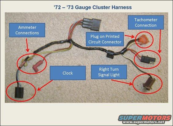 We have more pics and info here in this thread: http://forum.grantorinosport.org/info-72-79-gauge-clusters-and-wiring_topic2933.html" rel="nofollow - http://forum.grantorinosport.org/info-72-79-gauge-clusters-and-wiring_topic2933.html As your the tach, it sounds like someone may have bypassed yours. The two wire tach needs to be connected for the coil to work, if it hasn't been bypassed. Like I said, though, don't run a full 12 volts through that tach. What year is your car? that would help as there are wiring changes over the years. ------------- Vince 1972 Ford GTS Sportsroof - Survivor, One Family car GTS.org Admin |
Posted By: squarethumps
Date Posted: 11-May-2020 at 2:37PM
|
It is a 1976 (sorry I thought that was in the very first post). That thread you cited is a great source of information. I've looked at it numerous times for information. The picture you cited is the '72-'73 (or it is labeled as such), and the picture in that same post for the 1976 (posted below) doesn't seem to have the other end of the harness pictured, and it doesn't seem to have any other wires like the '72-'73 for the plug on the printed circuit connector, or the right turn signal light ( odd for that to be grouped with the tach/amps/clock ? ).  I did thing that _PERHAPS_ this was the harness I needed (no years is labeled ), albeit the "other" side of the connector that seems to be missing from mine, but I can't find anything that resembles it on the car currently, and more than that I can't even seem to find the hole in the firewall where it would go ?  |
Posted By: 72FordGTS
Date Posted: 11-May-2020 at 2:46PM
I am not overly familiar with the later cars wiring. There is a pic of that thread that shows your connector though. Look at the 74-76 cluster in this pic: That other harness you posted looks to be the right one IIRC. It comes through the firewall near the brake booster. See it in this pic below of my car but it is a 72.  ------------- Vince 1972 Ford GTS Sportsroof - Survivor, One Family car GTS.org Admin |
Posted By: squarethumps
Date Posted: 11-May-2020 at 3:00PM
| Wow I never noticed that black connector there in that picture of the back of the 74-76 cluster. It's hard to tell from the picture what is on the other side of that 6 pin connector. It looks like it was cut on the other side. But I do see it there. Another odd thing is that my schematic says that it is a grey connector and that one appears to be black. Nonetheless, that does seem to be the connector I'm missing. Unfortunately, it also seems that I'm missing the other side of that connector and all the wires / plugs that go through the firewall and splice into the other side of the coil wire. |
Posted By: squarethumps
Date Posted: 11-May-2020 at 3:17PM
Just so I am 100% clear, you are referring to the connector / firewall plug that, in the picture is leftmost in the picture, but when describing it on the car, one would say that it is more towards the passenger side of the vehicle. It is "closer" to where the brake booster mounts than the other firewall plug that we see in the picture of your '72, which is closer to the drivers side fender. Is that correct ? On my car, there doesn't even seem to be a hole in the firewall for a plug / harness to go there, so I'm really lost now. LOL |
Posted By: californiajohnny
Date Posted: 11-May-2020 at 3:23PM
|
was your car originally a sport cluster harness car, or are you converting to sport? ------------- JOHN 74 GRAN TORINO S&H CLONE 74 VETTE CUSTOM 90 S10 BLAZER 4X4 LIFTED 77 CELICA CUSTOM 75 V8 MONZA SUPERCHARGED 79 COURIER VERT. SLAMMED 75 VEGA V6 5 SPD 70 CHEV C10 P/U 68 MUSTANG FB CONVERSION |
Posted By: squarethumps
Date Posted: 11-May-2020 at 4:55PM
I am not sure what it originally was as far as the cluster goes. I know it's a 1976 #0022 S&H car. I have a Marti, but it doesn't say anything about the gauges. I acquired the car and the dash was already put together and it looked rather original, with the exception of a new dash "top". I have pictures of the body work that was done to the car, which includes floor pans and a repair of one of the door hinge posts, but nothing pictured that shows any kind of repair / replacement of the firewall. It's been about 4 years since I took apart the dash to figure out what was going on with the lack of power to the coil. I got sidetracked with other matters. I don't remember removing all of those pins from the connector when I removed the instrument cluster, and I'm inclined to believe that if I was taking out the gauge cluster and going to disconnect a harness, I wouldn't have had reason to remove all of those pins from their connector. I also don't really recall the tachometer working when I did get the car running originally but I think it was because we wired hot directly to the coil just to get the engine running. All that to say .. I'm not sure I guess, but the placement of the wires in their hold downs( clips and wire ties and such ) and the "crispyness" of the tape that was on the harness when it removed it for examination and repair, makes me to think that it was all original. |
Posted By: squarethumps
Date Posted: 12-May-2020 at 1:46AM
You know .. the more I look at that picture the more I think that the wires / firewall hole and plug you are talking about is actually to the "right" of the brake booster, that is, on the passenger side of the brake booster ? That looks to me like there are more of and the same color wires that I'm looking for ? Maybe that's where I'm making my mistake. I'll have to check later today. |
Posted By: 72FordGTS
Date Posted: 12-May-2020 at 12:36PM
|
That plug comes through on the driver's/left side of the booster. This is a '72, so they may have changed things by '76. It says in the description on your diagram "Engine compartment/LH side of dash". So it doesn't really narrow it down under the hood. Maybe John has a good pic of his firewall on his car? His is a '74 so it should be similar to yours. I am wondering if your car maybe didn't have the sport cluster originally? Was it listed on your Marti Report? Also BackinBlack just post a ' http://forum.grantorinosport.org/1974-gran-torino-instrument-cluster_topic18809.html" rel="nofollow - 74 to 76 style cluster for sale. He has a good pic of the back of his:  ------------- Vince 1972 Ford GTS Sportsroof - Survivor, One Family car GTS.org Admin |
Posted By: squarethumps
Date Posted: 13-May-2020 at 3:52AM
So first I was not clear that the gauge cluster I have is a sport cluster. I am gathering that it IS a sport cluster is that correct ? Secondly, I don't see anything at all about a "cluster" or instrument panel or anything relevant to the dash, or sport model mentioned in either the regular Marti report I have or the "Deluxe Report" that I have. It says that it is a Gran Torino 2-Door Hardtop built March 18th 1976, so an early '76 Torino. However, what I do notice is that the car originally came with Black Vinyl Bench seats, but when I acquired the car it has black / red stripe bucket seats. I wonder did the guy totally acquire a Gran Torino Sport interior and then put it into this car, and that's why I have this instrument cluster ? Again though, it just seems like the wiring and dash are all original to me ? 
|
Posted By: californiajohnny
Date Posted: 13-May-2020 at 4:53PM
|
ok, mine was a std cluster... i converted it! not sure if the std cars even had the hole for the short extra harness i'll look for a good pic... far as i know PS122 cars didn't come with sport clusters???( but i could be wrong? yes that red/lack interior is from the 74 sport there were 3 color options...black/red, tan/orange, and blue/lt blue idk if it specifically states on a marti about the cluster??? maybe someone else can chime in on that... a couple sport cluster cars i parted had that hole for the short harness on the drivers side of the booster between it and the main harness bulk head here's a pic of my firewall... no it does not have that hole! mine was a standard cluster car originally. i didn't buy the short harness... i wired it up myself instead  ------------- JOHN 74 GRAN TORINO S&H CLONE 74 VETTE CUSTOM 90 S10 BLAZER 4X4 LIFTED 77 CELICA CUSTOM 75 V8 MONZA SUPERCHARGED 79 COURIER VERT. SLAMMED 75 VEGA V6 5 SPD 70 CHEV C10 P/U 68 MUSTANG FB CONVERSION |
Posted By: californiajohnny
Date Posted: 13-May-2020 at 4:58PM
the speedo hole is to the right of the booster and below that is the column shift cable hole if you have a floor shift they may have put that connector plug out though it??? but idk if it would reach to plug in to the main harness? but who know what other people do and why ------------- JOHN 74 GRAN TORINO S&H CLONE 74 VETTE CUSTOM 90 S10 BLAZER 4X4 LIFTED 77 CELICA CUSTOM 75 V8 MONZA SUPERCHARGED 79 COURIER VERT. SLAMMED 75 VEGA V6 5 SPD 70 CHEV C10 P/U 68 MUSTANG FB CONVERSION |
Posted By: 72FordGTS
Date Posted: 14-May-2020 at 6:01AM
|
Since the gauge package/sport cluster was an option, it would be listed on the Marti report if your car had it. IIRC, some of the later GTS cars, 74-75 had the gauges as a standard feature, but the '72-73 didn't and off the top of my head, I don't think any 1976 Torino came with them standard either as teh GTS was gone in 1976. So based on what John posted I think your car probably didn't have a gauge package from the factory and someone tried to retrofit it. That's probably why both your car and John's don't have the hole in the firewall like mine. At this point, you might be better off to just wire it up on your own, without the harness, unless you are trying to make it factory correct. Anyone on here have a '74 to '76 Torino with the gauge package option from the factory? Maybe they can post a pic of the firewall too so we can confirm this info.
------------- Vince 1972 Ford GTS Sportsroof - Survivor, One Family car GTS.org Admin |
Posted By: squarethumps
Date Posted: 14-May-2020 at 6:07AM
|
So my firewall has the 2 holes to the right of the booster (towards the passenger side). The one closest to the booster has the spedo cable which goes to the transmission. The next one is the throttle cable. There are no other holes in the firewall. My car has a floor shifter. Again it seems to be original, but does it seem correct that the car would come originally with a bench seat AND a floor shifter for an automatic transmission ( C-6 )? That seems like something that they wouldn't have done. Would it help if I posted the Marti Reports ? Is there any danger in that ? The Marti report says that the car was ordered with a tilt steering column. The column that is in the car now does not appear to be a tilt style. I can't find where the "tilting" mechanism is. I mention all of this as part of the process of trying to figure out what is original on this car, and what has been changed out. The pictures I have of the body work just show the floor pans like I said but the "hump" in the middle seems to be original, and more than that there is a center console with the proper supports in between the bucket seats now. The screw holes for that must have been drilled / tapped after the bench seat was removed ? I'll pull up the carpet and take some pictures and maybe someone has an opinion on what is original or swapped. |
Posted By: squarethumps
Date Posted: 14-May-2020 at 6:16AM
Well, with all of those pins there on the back of my sport cluster, yes I would like to just be able to plug those into an original type connector and then have the wiring correct with the factory diagrams. A further concern I have is that if the wiring under the dash is original, but the instrument cluster is not, is there going to be issues with the main cluster connector ? Like, how different is the original wiring harness in the non-sport, vs the sport models, that might cause issues with the pins which basically connect to the cluster's printed green ribbon ? Or should that be fine and that is why these optional gauges ( tachometer, clock and ammeter ) are basically in a separate harness ? With respect to the non-sport cluster. I suppose then that the non-sport cluster did NOT have a tachometer at all ? I found this : but the colors of the wires for the tach are not perfectly matching with my diagrams so I would just remove the pins from that connector and put in my own. According to the picture I posted above with the C-209 connector, that is part of harness 10817 on the "other side" and the harness you see in the picture below is 10B942.  http://www.2040-parts.com/tachometer-wire-1974-1975-1976-ford-gran-torino-ranchero-mercury-montego-cougar-i1592284/" rel="nofollow - 10B942 for sale <SOO MUCH TO LEARN LOL> |
Posted By: californiajohnny
Date Posted: 14-May-2020 at 2:34PM
|
the main connector will fit i had to swap positions of 3??? wires in the connector unfortunately it was several years ago and i don't recall which ones??? i think it was the gas oil and water sending wires??? i took my std cluster and the sport and traced down each circuit on the board to the connector end and made notes then seen most were in the same location except those few, removed them from the connector and plugged them back into the new positions my brain works like a schematic but trying to explain that to someone can be impossible for me sometimes keep in mind the gauges that share a common connection to 1 pin will be the positive power side of the gauge the other side will have it's own separate pin will be the negative to that individual sender now on the turn lights and high beam those that share a pin will be the ground, each individual pin to that bulb will be the positive to it the dash bulbs will have a common ground pin location and common pin location for the power to them which is the light blue with a red stripe wire it should be in the same location on the main connector i believe so this may help to track down a few by process of elimination ------------- JOHN 74 GRAN TORINO S&H CLONE 74 VETTE CUSTOM 90 S10 BLAZER 4X4 LIFTED 77 CELICA CUSTOM 75 V8 MONZA SUPERCHARGED 79 COURIER VERT. SLAMMED 75 VEGA V6 5 SPD 70 CHEV C10 P/U 68 MUSTANG FB CONVERSION |
Posted By: squarethumps
Date Posted: 15-May-2020 at 5:30AM
@californiajohnny this is most distressing lol. I guess the light at the end of the tunnel is that I have the schematic I have and it seems like all the colors of the wires that it calls for are correct. So at least the wiring that is there is a "known". Then I can start to label out the pins on the sport cluster I have and compare that with the original wires and the connector that is there and see what needs to change. That is very good information you gave me about the shared positive and negative. I tried using a voltmeter and the continuity indicator ( the tone ) a couple years ago to try and see what was what, but with circuits like that, there's always some connectivity. It was trying to hear the difference between a loud buzz and a quiet buzz, and then try and interpret that meaning. Rather painful. That was before I got the schematic though. I need to get all the pages in that schematic copied and laminated or even scanned into a coherent digital format. |
Posted By: squarethumps
Date Posted: 15-May-2020 at 5:41AM
|
So .... All: I'm now looking for that connector that I'm missing from the 10B942 harness ( of which I have all BUT that connector ), AND I'm looking for the entire 10817 harness that goes through the firewall. I guess I will drill the correct size hole through the firewall to install everything properly. Of course I will only do that once I'm 100% sure that I have everything mapped out. Anyway .. does anyone have any of those connectors / harnesses ? <yinz have been quite helpful up to this point, thank you all so much> |
Posted By: handsofstone
Date Posted: 15-May-2020 at 10:06AM
|
Nevermind. I see the picrures. I had the wiring diagrams for one of my broncos. Pain in the butt to read it.
|
Posted By: squarethumps
Date Posted: 15-May-2020 at 11:29AM
Yes it took me a while to figure out what I was actually looking at. Now that I've gotten some help from a bunch of people I can at least study it and follow it and figure out what's what. |
Posted By: californiajohnny
Date Posted: 15-May-2020 at 12:23PM
|
i don't think i have any sport harnesses left but i'll look tonight i saw one dash harness still on a dash that had a bad fuse terminal so i didn't sell it... i'll look at it to remember which car it came from? ------------- JOHN 74 GRAN TORINO S&H CLONE 74 VETTE CUSTOM 90 S10 BLAZER 4X4 LIFTED 77 CELICA CUSTOM 75 V8 MONZA SUPERCHARGED 79 COURIER VERT. SLAMMED 75 VEGA V6 5 SPD 70 CHEV C10 P/U 68 MUSTANG FB CONVERSION |
Posted By: squarethumps
Date Posted: 15-May-2020 at 12:34PM
Thanks ! I appreciate all the effort ! |
Posted By: 72FordGTS
Date Posted: 16-May-2020 at 7:01AM
I found some a diagram that might be helpful for you: Also in the gauges thread there is some good info about converting from the standard cluster to the gauge cluster. The standard cluster does not have a tach, just a speedo, fuel, temp gauge and mostly warning lights. This is probably why your car didn't have the tach hooked up. I bet is was a standard cluster car and someone added the instrument cluster but did not connect the tach. This info might help you. The last two posts show the pins for the 74-76 standard cluster and the 74-76 instrument cluster.
------------- Vince 1972 Ford GTS Sportsroof - Survivor, One Family car GTS.org Admin |
 Psquare75 wrote:
Posted By: californiajohnny
Date Posted: 17-May-2020 at 11:15AM
|
i have that short sport harness!!! ------------- JOHN 74 GRAN TORINO S&H CLONE 74 VETTE CUSTOM 90 S10 BLAZER 4X4 LIFTED 77 CELICA CUSTOM 75 V8 MONZA SUPERCHARGED 79 COURIER VERT. SLAMMED 75 VEGA V6 5 SPD 70 CHEV C10 P/U 68 MUSTANG FB CONVERSION |
Posted By: squarethumps
Date Posted: 17-May-2020 at 11:28AM
YIPPIEEEEEEEE !!!!!! You are like the hero for the second time on this car man ! So you have the little one with the connector I am missing ? Or you have the other side of it that goes through the firewall ? Or BOTH ?!? |
Posted By: californiajohnny
Date Posted: 17-May-2020 at 11:44AM
|
i have the whole one like in the above pic that goes through the firewall i can look over the rest of the wiring and see if maybe there's a matching female connector that will work for your missing cluster one??? ------------- JOHN 74 GRAN TORINO S&H CLONE 74 VETTE CUSTOM 90 S10 BLAZER 4X4 LIFTED 77 CELICA CUSTOM 75 V8 MONZA SUPERCHARGED 79 COURIER VERT. SLAMMED 75 VEGA V6 5 SPD 70 CHEV C10 P/U 68 MUSTANG FB CONVERSION |
Posted By: californiajohnny
Date Posted: 17-May-2020 at 11:48AM
i have this one... ------------- JOHN 74 GRAN TORINO S&H CLONE 74 VETTE CUSTOM 90 S10 BLAZER 4X4 LIFTED 77 CELICA CUSTOM 75 V8 MONZA SUPERCHARGED 79 COURIER VERT. SLAMMED 75 VEGA V6 5 SPD 70 CHEV C10 P/U 68 MUSTANG FB CONVERSION |
Posted By: squarethumps
Date Posted: 17-May-2020 at 11:54AM
|
Oh that is fantastic !! Yes if you could find that other matching connector that would be amazing ! Yes I think you still have my address from the other PMs. Just send me a PM with the $ and I'll send it over. Also : @72FordGTS -- that information you posted is so appreciated ! I think that I will be able to read through all of that ( very slowly ! ) and pick it apart piece by piece. That sounds like about 16 - 24 hours of sleuthing and reading and examining and testing ! Quite a valuable resource. Thank you so much as well !! |
Posted By: californiajohnny
Date Posted: 17-May-2020 at 4:41PM
|
got it and a connector PM sent... ------------- JOHN 74 GRAN TORINO S&H CLONE 74 VETTE CUSTOM 90 S10 BLAZER 4X4 LIFTED 77 CELICA CUSTOM 75 V8 MONZA SUPERCHARGED 79 COURIER VERT. SLAMMED 75 VEGA V6 5 SPD 70 CHEV C10 P/U 68 MUSTANG FB CONVERSION |
Posted By: squarethumps
Date Posted: 28-November-2020 at 5:14AM
Ok fellas -- Yes, I know it ( again ) has been a while -- but -- I can finally give some attention to this, which I have. I have examined the P.C. printed circuit ('74 Sport - there's a picture on page 1 of this thread ). I have also examined the wired pin connector on the car, which is believed to be original to the '76 S&H, and compared it to both the existing wiring schematic that I have, and the post above, which I've quoted. It took me a little time to map out everything, but I think I have it fairly understood with a few exceptions. I'm not sure how best to do this, so I will describe each pin "position" with respect to what is, what was, what is to be, and what should never be :) I should note that the '74 Sport Gauge Cluster I have has 5 illumination lights, 1 (one) brake light positioned at the center top of the tachometer, 1 (one) high beam light positioned at the center bottom of the tachometer, 1 (one) each left and right turn signal indicators positioned on either side of the high beam indicator, 1 (one) Fasten Seat Belts light, and 1 "Low Fuel Economy" light. ( The previous post, nor other posts, say nothing about this "Low Fuel Economy" light indicator, so I'm not sure on this one. Nonetheless, the dash cover I have clearly has a green "Low Fuel Economy" light above the red "Fasten Seat Belts" light. There is also not an "alternator light socket" on my cluster ? The previous post says that pins 10 / 11 both go to the alternator light socket. I don't have one of those lights, and you will read below about positions 10 and 11 and my confusion about what to do with them. '74 Sport Gauge Cluster - hereafter '74 SGC '76 Wiring Schematic / Car - hereafter '76 WS POSITION 1 '74 SGC - positive(+) side of brake light '76 WS - Circuit 640 - Red w/ Yellow Hash - seems to have an end at a "Low Vacuum Warning Indicator Lamp" and then also goes through the firewall blocks to the "Carburetor Throttle Emission Control Solenoid" and also to the "Distributor Modulator Valve". Additionally, inside the car, that circuit 640 is connected directly to the "Protection & Convenience, Seat Belt Warning Buzzer", and also ends at F-11 (fuse I think). ( the other side of the fuse is part of the coil + ) Analysis : The wire from position 14 needs to be here instead. POSITION 2 '74 SGC - negative (-) side of Temperature Gauge '76 WS - Circuit 450 - Dark Green with Light Green Stripe - seems to be labeled as connected to the Seat Belt Warning Indicator Lamp on the P.C. and the Seat Belt Warning Indicator Switch. (Is this the positive side for the Fasten Seat Belts light? ) Analysis : Move this wire to position 13, and move the wire from position 12 (negative temp gauge wire) to this spot. POSITION 3 '74 SGC - positive (+) of the dash illumination lights '76 WS - Circuit 19 - Blue with Red Stripe - positive (+) from fuse Analysis - no changes needed POSITION 4 '74 SGC - negative (-) of dash illumination, high beam indicator light, and turn signal indicator lights '76 WS - Circuit 57 - Black - negative (-) connected to a lot of other negative wires and ground. Analysis - no changes needed POSITION 5 '74 SGC - positive (+) of the Right Signal Indicator '76 WS - Circuit 2 - White w/ Blue Stripe - Right Turn Signal positive (+) Analysis - no changes needed POSITION 6 '74 SGC - positive (+) of the Left Signal Indicator '76 WS - Circuit 3 - Light Green w/ White Stripe - Left Turn Signal positive (+) Analysis - no changes needed POSITION 7 '74 SGC - positive (+) of the High Beam on Indicator '76 WS - Circuit 12 - Light Green w/ Black Stripe - High Beam positive(+) Analysis - no changes needed POSITION 8 '74 SGC - Seems to be the common POSITIVE (+) to the gauges ( Fuel, Oil Pressure, Temperature ) '76 WS - Circuit 297 ( There is also the number 48 there ? I can provide pic if desired ) - Black w/ Blue Stripe is what is actually in the car. The schematic says it should be a Black w / Light Green Hash ?? - but it seems to be part of the circuit which comes from the key switch, and is off when the key is in the "start" position, and on when the key is in any of the other positions ( except "Off") Analysis - no changes needed POSITION 9 '74 SGC - negative(-) side of the Fuel Gauge '76 WS - Circuit 29 - Yellow w/ White Stripe - Fuel circuit Analysis - no changes needed POSITION 10 '74 SGC - negative (-) side of the Oil Pressure Gauge '76 WS - Circuit 904 - Green w/ Red Stripe - This circuit seems to carry the voltage to the regulator, and originally went to the coil then also? It is connected to the (Green w/ Red Hash ?) wire from position 11. Analysis - The wire from position 13 (White w/ Red Stripe) needs to be moved here, but I'm not sure where this wire should be moved to. POSITION 11 '74 SGC - There is NOTHING here - not even a copper tab on the P.C. '76 WS - Circuits 904 AND 687. Circuit 687 is a Grey w/ Yellow Stripe wire which goes to the ignition switch. Circuit 904 ends up connected to the wire from position 10, so again this is confusing as to what I should do with it. Analysis - I have no idea what to do here ? POSITION 12 '74 SGC - positive(+) side of the "Low Fuel Economy" light - but NOTE the picture : there is a BREAK in the printed circuit ?? WHY ?? '76 WS - Circuit 39 - Red w/ White Stripe - negative (-) to the Temperature sending unit. Analysis - move the Red w/ White Stripe to position 2 to match the printed circuits / cluster. Not sure what wire to move here ? POSITION 13 '74 SGC - positive(+) side of the Fasten Seat Belts light '76 WS - Circuit 31 - White w/ Red Stripe - negative (-) to the Oil Pressure Sending unit. Analysis - move the White w/ Red Stripe to position 10 to match the printed circuits / cluster. The Dark Green w/ Light Green stripe wire from position 2 moves here POSITION 14 '74 SGC - seems to be the common (-) negative for the lights for the Brake light, the Low Fuel Economy light, and the Fasten Seat Belts light. '76 WS - Circuit 977 - Purple w/ White Stripe - positive(+) side of the brake light Analysis: Move the wire to position 1. I'm not sure if I should swap this with the wire from position 1 though, but I think I should. In summary, I think that Wires 1 and 14 can be swapped. Wire 2 moves to position 13 Wires 3-9 are correct and can stay. Wire 10 gets moved to ?? Wire 11 gets moved to ?? Wire 12 moves to position 2 Wire 13 moves to position 10. Wire 14 (again) is swapped with 1. I really appreciate anyone who reads this and offers advice or corrections. I will supply any pictures or further descriptions that are requested. PS. as far as the Tachometer, rather than punch a hole through the firewall, or chop the end off of the harness that California Johnny sent, I will find a plug that I will simply connect to that end, and then run the tachometer wires through the existing firewall blocks ( C-401 or C-402 ) in holes / positions which are unused. I will also hook up the ammeter wires in similar fashion. Those items, and the clock tap are separate from the rest of the instrument cluster which I'm discussing above. |
Posted By: californiajohnny
Date Posted: 28-November-2020 at 1:35PM
|
not sure on the fuel light and belts light far as i know they were separate wire to the bezel not in the cluster main plug to the circuit board? i swapped 74 sport to 74 std harness ... i recall swapping positions of 3 wires in the main connector plug gas, oil, and water i think? it was like 7 years ago... what i did was trace down each circuit along the PC to the connector and labeled it with a letter with a sharpie or make notes on paper , but if you dont have both clusters to compare it would make it more difficult ------------- JOHN 74 GRAN TORINO S&H CLONE 74 VETTE CUSTOM 90 S10 BLAZER 4X4 LIFTED 77 CELICA CUSTOM 75 V8 MONZA SUPERCHARGED 79 COURIER VERT. SLAMMED 75 VEGA V6 5 SPD 70 CHEV C10 P/U 68 MUSTANG FB CONVERSION |
Posted By: squarethumps
Date Posted: 28-November-2020 at 3:07PM
|
yes that's right .. I did the same thing with my P.C. by tracing the connections and using your advice that the gauges share a common positive, while all the lights share a common negative, this makes a lot of sense. It was those two wires ( 3 really ) the green with the red stripe and the grey with the yellow stripe that are the confusing ones. I've moved those to the spots where there are basically no connections to the P.C. ( no loop either ) I'm not sure if this is 100% correct as we will see. Soooooooo .... I made those changes as follows : wire 1 swapped with wire 14 wire 2 moved to position 13 wire 3 - 9 no changes wire 10 moved to position 11 ( the dead spot ) wire 11 moved to position 12 ( basically another dead spot ) wire 12 moved to position 2 wire 13 moved to position 10 wire 14 (as above) swapped with wire 1. I plugged it in aaaaannnd !!!! weeeell .. I decided to test the cluster illumination lights first ( the headlight switch already works to turn on the illumination lights behind the climate control, and the dome light works from that switch too ) it looks like ONE of the cluster illumination lights is working .. the one that is over by the ammeter. soooo ... ( sorry .. I started investigating ) ... So I had bought and installed new LED backlights .... turns out that these lights only work ONE way, even though they fit both ways ( like . 180 degrees out ) .. so ... so far I've found one defective LED light, and 3 of the sockets are working !! So I'm going to keep playing and testing things and I'll provide an update soon . I also tested the Oil Pressure gauge by just grounding the wire in the engine bay directly to the engine block / ground, and the oil gauge went up to just below 90, which I imagine might be just about as far as that old gauge can go. I'm calling it a success and working ! I tested the temperature gauge ... it's not working, at least when I ground the wire at the same connector in the engine bay as the oil pressure wire ( the oil pressure, coil wire, and temperature wire all travel through the same connector in the engine bay ) so I will test this by grounding out the terminal wire directly behind the cluster 14 pin connector wire in position 2 and see if the gauge moves. so ... there has been some success and I'll keep updating |
Posted By: californiajohnny
Date Posted: 28-November-2020 at 5:07PM
|
yes led's are one way, just 180 the sockets, also you may need to bend up the little tabs in them so they make snug contact with the pc also if the bulbs have just thin tiny wires that go into the socket you may need to bend the wire part with a slight sideways angle so they contact in the sockets( usually those type slide off the contact when you put the bulb in the socket) ------------- JOHN 74 GRAN TORINO S&H CLONE 74 VETTE CUSTOM 90 S10 BLAZER 4X4 LIFTED 77 CELICA CUSTOM 75 V8 MONZA SUPERCHARGED 79 COURIER VERT. SLAMMED 75 VEGA V6 5 SPD 70 CHEV C10 P/U 68 MUSTANG FB CONVERSION |
Posted By: Steve M.
Date Posted: 29-November-2020 at 1:44AM
|
Here is what I discovered doing the standard to sport cluster change. I've done it to all 5 of my Gran Torino's. The '72 and '73 were by far the easiest. No changes needed to the main connector. The '75 to '74 required the oil and temperature gauge locations switched in the cluster. The early model '76 went just like the '75. This latest '76 is all by itself. Looks like your at the same point I was at. My temperature gauge circuit was open until I got it right. My gauge was bad too. It was a bit unnerving at first. The good news is all of the colour codes from '74-'76 haven't changed. ------------- Steve M. |
Posted By: squarethumps
Date Posted: 29-November-2020 at 2:39AM
This is EXACTLY what the issue was on a few of the LEDs. They were 180 out of position and a few of the little wires did bend out and were not making contact. Results : ALL the illumination lights work !!  |
Posted By: squarethumps
Date Posted: 29-November-2020 at 2:46AM
|
so .. since the illumination lights are working I started testing the gauges. I suppose I should also note that when I turn on the key I don't get the buzzer, and none of the other lights light up ( fasten seat belts I would expect ) so that will need to be sorted. The oil pressure gauge works perfectly. I grounded out the wire all the way at the end where it actually connects to the sending unit and the gauge spiked up. 1 down ..a bunch to go ! The temperature gauge itself works but something is up. I ran a negative from the battery directly to negative side of the gauge post, and it works. Then I tested it on the back of the connector by jamming the ground wire directly into the #2 position wire ( which is now the White with Red stripe wire ), and again the gauge moves. This tells me the problem is not in the cluster or gauge, but in the White w/ Red stripe wire somewhere between the cluster and that terminal end in the engine bay. (Is there a fuse ? ) In any case, at least the gauge and cluster P.C. works. Coincidental that you had an open circuit there too Steve M. I will investigate and see what I can figure out. I will probably test the fuel gauge next. |
Posted By: Steve M.
Date Posted: 29-November-2020 at 2:50AM
I found this.  ------------- Steve M. |
Posted By: Steve M.
Date Posted: 29-November-2020 at 2:56AM
|
I used this to get the wires to double check how I was going to get my wires to the correct gauges. Interesting enough, my car doesn't have the microswitch for the e-brake. The connector is there should I wish to install it ------------- Steve M. |
Posted By: Steve M.
Date Posted: 29-November-2020 at 3:19AM
Like the steering wheel. I used one from a Mustang ll Stallion package.  ------------- Steve M. |
Posted By: Steve M.
Date Posted: 29-November-2020 at 3:21AM
|
Love the LEDs! ------------- Steve M. |
Posted By: californiajohnny
Date Posted: 29-November-2020 at 4:49AM
|
could be the little voltage regulator on the pc??? mine didn't read right or something so i ended up using the one from my std cluster, it had to be mounted opposite to bolt on ------------- JOHN 74 GRAN TORINO S&H CLONE 74 VETTE CUSTOM 90 S10 BLAZER 4X4 LIFTED 77 CELICA CUSTOM 75 V8 MONZA SUPERCHARGED 79 COURIER VERT. SLAMMED 75 VEGA V6 5 SPD 70 CHEV C10 P/U 68 MUSTANG FB CONVERSION |
Posted By: Steve M.
Date Posted: 29-November-2020 at 4:53AM
|
Hey John, Is there anything you haven't done on one of these yet? ------------- Steve M. |
Posted By: squarethumps
Date Posted: 29-November-2020 at 4:55AM
This is a very helpful diagram, thank you. |
Posted By: Steve M.
Date Posted: 29-November-2020 at 5:02AM
|
I'm digging through a folder of old papers on my car to find this stuff. The idea of doing another one is in the back of my mind. On my '73, we cut the rusted roof off and installed one from a '78 T-bird with T-tops. There was a lot of beers on that one. ------------- Steve M. |
Posted By: squarethumps
Date Posted: 29-November-2020 at 5:06AM
Hi John, I'm not sure what you mean here ? I think mine is ok, because when I put a direct negative wire into the position #2 which is the negative side of the temperature gauge, the gauge goes right up to maximum, which is what I would expect. |
Posted By: squarethumps
Date Posted: 29-November-2020 at 5:07AM
Oh WOW T-TOPS on a torino !! that would be cool !! got pics ? |
Posted By: 72 RS 351
Date Posted: 29-November-2020 at 7:47AM
That sounds like a cool deal. Way back when I dreamt of adding a sunroof from a Honda Civic(the tiny hatch back in 1989), for my Ranchero. I like fun ideas. ------------- Don 73 Ranchero "Sport 72 front end", floor shift/console, planning EFI 7000+ rpm 351-4V &4R70W 73 Ranchero GT 351C-4V &4R70W for sale later. 92 Lincoln Mark VII SE GTC, OBDII 347/4R70W |
Posted By: californiajohnny
Date Posted: 29-November-2020 at 1:28PM
|
i don't remember what the issue was but i swapped the regulators and it worked better? i think it's more for the fuel gauge than anything? ------------- JOHN 74 GRAN TORINO S&H CLONE 74 VETTE CUSTOM 90 S10 BLAZER 4X4 LIFTED 77 CELICA CUSTOM 75 V8 MONZA SUPERCHARGED 79 COURIER VERT. SLAMMED 75 VEGA V6 5 SPD 70 CHEV C10 P/U 68 MUSTANG FB CONVERSION |
Posted By: squarethumps
Date Posted: 29-November-2020 at 1:39PM
Ahh .. I see. Well, I don't actually have the original cluster. All I have is this sport cluster that came with it when I acquired the car. I guess I will see what happens ? I manually tested the 3 gauges, and they all work and only work when the key is ON so that is good anyway. As I said before, the oil pressure gauge wires all seem to be A-OK because when I ground the end of the wire that connects to the sending unit, the gauge goes up. That one is DONE. Next is to start tracking down where the wire for the Temperature starts/stops working. |
Posted By: squarethumps
Date Posted: 30-November-2020 at 7:47AM
|
http://forum.grantorinosport.org/forum_posts.asp?TID=16377&PID=208064&title=1976-gran-torino-coil-oil-pres-temp-conne#208064" rel="nofollow - http://forum.grantorinosport.org/forum_posts.asp?TID=16377&PID=208064&title=1976-gran-torino-coil-oil-pres-temp-conne#208064 Guys, have a look at this other thread where I was discussing the connector under the hood which I _thought_ was for the coil, oil pressure and temperature gauge. I have a correction which I will also post here : Indeed there is a COIL wire ( Red with Light Green stripe ) and the OIL PRESSURE wire ( White with a Red stripe ) are there and they are correct. (Though I think that coil wire will come in to play later on when I am sorting out the tachometer .. there is another wire ( Red w/ Light Blue ) that goes nowhere and I think should do something with the coil / tach wire .. more on that later ) However, that THIRD wire - the Red w/ Yellow Hash - I somehow incorrectly identified that wire as the negative side of the Temperature gauge. ( Well I know how .. it's because I plugged in the dash cluster before I ever knew it was not original to the car and my testing results were obviously wonky ). In any case .. that connector does NOT contain the wire which goes to the temperature sending unit. There was another loose wire hanging about from the firewall plug .. a Red w/ White stripe ( imagine that lol ) and when I connect it directly to ground .. BOOM the temperature gauge WORKS. In any case, both the Oil Pressure gauge and the Temperature Gauge are now correctly identified and sorted. So now I need to figure out exactly what that Red w/ Yellow Hash wire is all about. On the schematic in the engine side, it shows that wire going to some vacuum sensor and indicator light ( the light is in the cluster ? trying to understand that ? ) and also it goes to some emission control switch located on the carburetor ?? So I know that my carb doesn't have any sensors or electrical switches other than the electric choke, which I thought was part of the alternator wiring somehow ? So there is still more sorting to do here. |
Posted By: squarethumps
Date Posted: 30-November-2020 at 8:12AM
|
sorry for the multiple posts guys. I'm just talking through it as I sort it out. So ... that Red w/ Yellow Hash wire in the connector under the hood .. still not sure .. but I read on the schematic, and as we've discussed here, that same color wire ( Red w/ Yellow Hash ) started out in position 1 and I have now moved it to position 14. However, even connecting this wire under the hood to negative ground seems to have no effect. Furthermore -- ( even without that wire being connected to anything in the engine bay ) I have discovered that when I press the brake pedal ( even with the key OFF ) that ALL the illumination lights come ON. ( Not the dome light ) The 5 illumination lights in the main cluster AND the illumination light behind the climate controls all come ON when I press the brake pedal. So .. now I'm really confused as to what is going on. I guess the thing to do is to follow each side of the brake pedal switch and see where each side goes to understand how this is happening ? <If I haven't before, allow me to state how much of a PITA electrical issues are for me.> |
Posted By: californiajohnny
Date Posted: 30-November-2020 at 1:36PM
|
i've seen the red w/yellow wire before... don't recall what it went to??? some cars had different lights on the side of the bezel low fuel econ, door ajar, brake i think? which you may not even need. it could be for the a/c idle dashpot solenoid? ------------- JOHN 74 GRAN TORINO S&H CLONE 74 VETTE CUSTOM 90 S10 BLAZER 4X4 LIFTED 77 CELICA CUSTOM 75 V8 MONZA SUPERCHARGED 79 COURIER VERT. SLAMMED 75 VEGA V6 5 SPD 70 CHEV C10 P/U 68 MUSTANG FB CONVERSION |
Posted By: squarethumps
Date Posted: 30-November-2020 at 2:01PM
It very well could be. Investigating that wire under the hood, and also realizing that the red w/ white stripe wire is the temperature negative, made me check out this other wire that was just hanging in the breeze. It was the red w/ light blue stripe wire !! ... seeing that totally jarred my brain cells and I remembered that wire was like part of the ignition circuits. So I actually still have some more understanding and study to do to really grasp what is here on the car and what is missing. That ignition circuitry includes the connection to the tachometer which is on the engine side of the firewall .. that investigation is pending. new fun -- as I described in the post above, all the illumination lights would turn ON ( even with the key OFF ), when I would press the brake pedal. It's no longer doing that, and I've changed nothing ! lol .. I love problems that come and go by themselves. Unfortunately, it probably means an intermittent short somewhere I need to find. ugh .. issue upon issue with the electrical. |
Posted By: californiajohnny
Date Posted: 30-November-2020 at 3:48PM
|
red blue stripe iirc one of the tach wires is that color? dash lights are lt blue w/red stripe! thats weird they come on like that, must be something jumped somewhere??? could be an incorrect bulb jambed in a socket somewhere.... ------------- JOHN 74 GRAN TORINO S&H CLONE 74 VETTE CUSTOM 90 S10 BLAZER 4X4 LIFTED 77 CELICA CUSTOM 75 V8 MONZA SUPERCHARGED 79 COURIER VERT. SLAMMED 75 VEGA V6 5 SPD 70 CHEV C10 P/U 68 MUSTANG FB CONVERSION |
Posted By: squarethumps
Date Posted: 01-December-2020 at 12:13PM
|
so that's what I get for taking so long to get back to this project. There are TWO Red w/ Light Blue wires, both in different positions in the blocks that go through the firewall. ( one on each of them in fact )and I forgot about that. One of them, along with the White w/ Light Blue Hash wire used to go to the Ignition Modulator. This car no longer has that or needs it, I guess. These two wires are on firewall connector C-401A which is the passenger connector which carries all the lighting wires for the front of the car. The other red w light blue wire correctly goes to the Starter Relay. So .. something I should have done before trying to sort out all the wiring is to take the cluster and make sure that I have all the bulbs working and turned the right way. It may be that the brake light bulb isn't in correctly. Also -- I found that I don't even have a buzzer in the car ! It was removed by someone. So .. I need a working buzzer to install. Recommendations ? Thanks for all the help. |
Posted By: californiajohnny
Date Posted: 01-December-2020 at 6:47PM
|
i may have a good buzzer... i saw one the other night in the garage ------------- JOHN 74 GRAN TORINO S&H CLONE 74 VETTE CUSTOM 90 S10 BLAZER 4X4 LIFTED 77 CELICA CUSTOM 75 V8 MONZA SUPERCHARGED 79 COURIER VERT. SLAMMED 75 VEGA V6 5 SPD 70 CHEV C10 P/U 68 MUSTANG FB CONVERSION |
Posted By: squarethumps
Date Posted: 02-December-2020 at 6:56AM
I looked through all the spare parts boxes I have and I don't seem to have one so .... how much might you be asking for said buzzer ? lol. feel free to PM. |
Posted By: squarethumps
Date Posted: 05-December-2020 at 9:19AM
|
couple of questions for my sanity. The key switch -- should I be able to turn it "backwards" from the OFF position ? The keys in all the cars I remember my parents having ( I was born in '76) you could turn it "backwards" to an Accessory position. Or was that a feature in 80's cars ? Secondly, IIRC, the brake light, the fasten seat belts light and possibly any other lights should come ON when I turn the key to the "RUN" position, which on this car does seem to be 2 clicks past OFF. correct ? ( those are the only two lights that I have which would light on my dash cluster .. still trying to figure out why there is a break in the circuitry on the printed circuit for the positive side of that one light at position 12 ) I know that the brake light works because when I manually ground the parking brake wire ( the parking brake switch isn't working ), then the brake light will come ON. The other light, the fasten seat belts light, I would also expect to come on, but granted, I haven't traced down that positive wire, and the seat belt buckles are not in the car, which is where the switch would be I would guess? |
Posted By: squarethumps
Date Posted: 05-December-2020 at 10:48AM
|
Additionally I've figured out that the seat belt buzzer, which is in fact different than the ignition buzzer, is not working. I am getting power to the seat belt buzzer, but when I directly ground the single wire which goes to the seatbelt retractor, even at the connector itself, the buzzer does not buzz. I've also made sure that the black wire, which provides a constant ground to the buzzer, is indeed connected to ground. So .. I ordered up a new OEM buzzer, that I got pretty cheap on ebay. one more piece of the puzzle sorted. |
Posted By: squarethumps
Date Posted: 06-December-2020 at 3:07PM
|
My clock doesn't work, and I see now that my ashtray cover ( the black part which constitutes the part of the dash which is visible ) is broken off. I'm looking for a working clock and a whole ash tray if anyone has those. |
Posted By: handsofstone
Date Posted: 06-December-2020 at 5:19PM
|
Turn the key back and it is accessory. Forward to ignition and brake and alt. light are glowing red. Circuit board can be repaired if you cannot find a replacement. Solder is your friend. Just be careful. CJ probably has the ashtray assembly but you may have to paint it to match.
|
Posted By: squarethumps
Date Posted: 06-December-2020 at 5:27PM
|
ok .. so why might my key not turn "backwards" ? Is the problem in the key barrel part itself or in the ignition switch with the rod behind the gauge cluster ? I'll know more about the lights and buzzer working with the key movements after I get the new seat belt buzzer installed. The wires all seem to be good, just that buzzer is busted. Thanks |
Posted By: handsofstone
Date Posted: 06-December-2020 at 5:42PM
| How far does the cylinder move back from off position? I remember replacing the switch on my first GTS back in high school and adjusting it wasn't too tricky. How far do you have to roll the cylinder for start? It is about parallel to the column when starting I believe. Could you could be in acc. when locked. |
Posted By: californiajohnny
Date Posted: 06-December-2020 at 7:25PM
|
pm'd you on the ashtray... got a blk one ready to go john is right about the switch down on the column... do the other notches feel right? could be the switch too??? i've sold a few to guys... ------------- JOHN 74 GRAN TORINO S&H CLONE 74 VETTE CUSTOM 90 S10 BLAZER 4X4 LIFTED 77 CELICA CUSTOM 75 V8 MONZA SUPERCHARGED 79 COURIER VERT. SLAMMED 75 VEGA V6 5 SPD 70 CHEV C10 P/U 68 MUSTANG FB CONVERSION |
Posted By: squarethumps
Date Posted: 07-December-2020 at 12:51PM
|
So .. the other notches do feel right, I _think_. Yes the "start" position does seem to be parallel with the column, and I do feel the "forward" Acc position, and also the Run position click into place, and I believe that these are good. I think a good way to test this is to test the blue w red stripe wire which goes to the radio. It should be charged 12+ when the key is in both the Acc and the Run positions. ( And also the backwards Acc position IF I could get the key to turn backwards ) but the ignition wire which goes to the coil should only be charged in the "Run" position I believe. When I try to turn the key backwards from the Off position ( I am sure it is the off position because I can easily take the key out ), it just .. kinda feels .. jammed. like it's kinda threatening to turn, kinda springy, I can see the rod which goes to the ignition switch sort of wiggling, but no movement. I have another ignition switch too which I replaced when I had no idea what all these wires really did ( now I know  ). Perhaps I can look at it and see if it allows movement of the switch in that direction. ). Perhaps I can look at it and see if it allows movement of the switch in that direction. |
Posted By: californiajohnny
Date Posted: 07-December-2020 at 1:43PM
|
lt blu w/ red stripe should be dash lights now you got me thinking.... i'll have to go out to the garage and check positions on my car....hmm ------------- JOHN 74 GRAN TORINO S&H CLONE 74 VETTE CUSTOM 90 S10 BLAZER 4X4 LIFTED 77 CELICA CUSTOM 75 V8 MONZA SUPERCHARGED 79 COURIER VERT. SLAMMED 75 VEGA V6 5 SPD 70 CHEV C10 P/U 68 MUSTANG FB CONVERSION |
Posted By: squarethumps
Date Posted: 07-December-2020 at 1:52PM
|
yes - sorry for the misinformation above ... the blue w red stripe is for the illumination, and does indeed get 12v+ when the light switch is pulled out. It is the yellow with black hash wire which carries the power when the key is either in the Acc or the Run positions, according to the schematic I have. It is currently only carrying power when the key is in the Run position. Thinking a bit more .. would there be a difference from '74 to '76 for the key functionality ? I would guess not, but it's possible that the column also came out of the '74. I would still suppose the key mechanically moves the same. btw .. that yellow with black hash wire connects to the fuse panel ( which reminds me .. it's really funny ... this seemingly authentic schematic I have seems to be very accurate in the first pages .. but towards the end, in the "Protection and Convenience" sections and beyond, I find more and more mistakes. Fuse #s wrong, "D" or "H" missing when describing the circuit wire color .. odd ) The power for the other side of the fuse apparently comes from the single black with light green hash from the ignition switch. Have a look here at the schematic :  The yellow with black hash ( circuit 137 ) is the radio power and connects through fuse F-1 to the single black with light green hash wire. I think the schematic says that all of these wires ( both spots on the connector ) should be 12v+ in either the ACC or the RUN positions. On my car, in the ACC position, none of those wires are 12v+, but in the RUN position, they are 12v+. 
|
Posted By: squarethumps
Date Posted: 07-December-2020 at 2:29PM
|
Hmm .. the labels of those positions on the switch might give me a clue, and maybe someone can confirm ? The positions state ACC LOCK OFF RUN START ... and the wiring shows that the black w/ light green hash wire is hot in the ACC and RUN positions, but does not show it hot in the OFF position. Am I expecting the wrong thing here ? I thought that the radio always came on with forward position 1 ( 1 out of 3, the other two being RUN and START ) on these old cars ? Is that wrong ? does the radio only come on when the key is in the "backwards" ACC position? ( and RUN of course ) ? |
Posted By: handsofstone
Date Posted: 07-December-2020 at 3:03PM
| If the radio only came on in accessory, how would you listen while cruising? |
Posted By: californiajohnny
Date Posted: 07-December-2020 at 5:41PM
|
i believe it's on in the on position and the acc position. btw yes my key turns back from the lock position for acc ------------- JOHN 74 GRAN TORINO S&H CLONE 74 VETTE CUSTOM 90 S10 BLAZER 4X4 LIFTED 77 CELICA CUSTOM 75 V8 MONZA SUPERCHARGED 79 COURIER VERT. SLAMMED 75 VEGA V6 5 SPD 70 CHEV C10 P/U 68 MUSTANG FB CONVERSION |
Posted By: squarethumps
Date Posted: 08-December-2020 at 2:28AM
sorry .. my sentences were a bit wacky .. and my assumptions too ... but yes .. I was asking if the radio only came on in the backwards "ACC" position AND the RUN position. But the diagram I have, and others observations, seem to state that it should come on in ACC position and RUN position. It seems that there is no forward ACC position ? There must be something wrong with my ignition switch that it won't allow the key to turn backwards, and the "ACC" position might not be messed up .. if I can get the key to turn. I will loosen the nuts that hold it down tonight and see if I can figure it out. |
Posted By: squarethumps
Date Posted: 08-December-2020 at 2:32AM
so does that mean that your first forward position is in fact NOT an ACC position ? it is the OFF position and the radio does NOT come on ? It only has power in the backwards position (ACC) and the second position forward (RUN) ? |
Posted By: squarethumps
Date Posted: 08-December-2020 at 5:33PM
|
So I completely removed my ignition switch and I still could not finegle ( how does one spell finagal ? ) the key into the backwards "ACC" position. Is it possible that the column I have doesn't allow this ? or is it much more likely that something is afoul inside the key barrel or ( I don't even know what's in there yet )  I have verified that the ignition switch itself does in fact have the positions for ACC from backwards and only in that position, and the RUN position, do the pins for black with green hash wires become continuous with the positions for the yellow wires ( which carry the constant 12v+ ). So the ignition switch would work .. IF the key could turn backwards. another puzzle to solve. I'm waiting for a buzzer and some other lights to arrive anyway. I also need to put in a new heater box resistor. |
Posted By: 72 RS 351
Date Posted: 09-December-2020 at 4:03AM
|
I believe you need a new ignition key cylinder. Those have fragile parts inside that after decades, will eventually fail. It's a good time now to replace all of those in older cars. If the key is lost or the cylinder fails and doesn't allow it to turn to RUN, you will have to destroy the cylinder to remove it. That can also damage the column, which is an even bigger issue. So hunt a new key cylinder, whether OEM or a good aftermarket unit. That should help a lot. ------------- Don 73 Ranchero "Sport 72 front end", floor shift/console, planning EFI 7000+ rpm 351-4V &4R70W 73 Ranchero GT 351C-4V &4R70W for sale later. 92 Lincoln Mark VII SE GTC, OBDII 347/4R70W |
Posted By: handsofstone
Date Posted: 09-December-2020 at 4:16AM
| Do not destroy the cylinder or the column trying to remove it. There is a small slot under the turn signal switch that is paper thin that you just poke a small flat screwdriver through and the key cylinder pops out. |
Posted By: handsofstone
Date Posted: 09-December-2020 at 4:25AM
 
|
Posted By: squarethumps
Date Posted: 09-December-2020 at 4:30AM
|
THANK YOU for that pic. I wonder if I can get a barrel which matches my existing key ? actually I'd like to have an original OEM key barrel and lock set. |
Posted By: squarethumps
Date Posted: 09-December-2020 at 4:40AM
| actually -- based on your statements ... would it be smarter to get an aftermarket key tumbler ? Would an OEM one be subject to the same deterioration sitting in the box on a shelf for the last 30 years ? |
Posted By: handsofstone
Date Posted: 09-December-2020 at 5:11AM
| There were many vehicles using the same part. I doubt they would just deteriorate over time. They are most likely in some storage room with all the other parts we use. |
Posted By: handsofstone
Date Posted: 09-December-2020 at 5:22AM
I would imagine you could get a matching key setup by making a lot of calls to dealerships across the country. I would just get a complete set for ignition and doors from John.
|
Posted By: 72 RS 351
Date Posted: 09-December-2020 at 6:58AM
Yes but, the cylinder will only come out when it is turned to the RUN position. That tiny pin only can be pushed in when the key is turned to RUN. That means it better not fail in any other position, and if you have no key, you cannot turn it to RUN. Any key cylinder can be re-pinned to match any key. The tumblers inside are replaceable and come in about six different versions. Any locksmith can repin the cylinders, when they are out. They take them apart and change the tumblers. So in theory if the old cylinder has only wear to the tumblers, you might be okay to have the tumblers replaced. But the cost of a new cylinder is not ridiculously high, many aftermarket choices will be $30 to $50. Some locksmiths will charge something to come to you, onsite like a windshield. I had one come to me in a parking lot in 2007, for two cylinders. It was $40 plus the re-pinning, about $75 as I recall. He was there about 15 minutes, and I was having him do a new ignition key cylinder(OEM 99 Explorer about $70), and a rear hatch used cylinder. I would not reuse a 25+ year old key cylinder if I had a choice. The headache of dealing with one failed cylinder will teach you that if you haven't experienced it already. If you find a NOS key cylinder, buy it if the price is good. Time doesn't hurt these things, turning the key inside them excessively does. Ask your mail carrier how many times each day he/she turns the ignition key from off to start. Due to ongoing run away accidents, a new policy began almost ten ears ago. If the person has to get out of the seat, the key has to come out of the ignition. That means starting and stopping the engine about 40-50 times a day. That accelerates the wear on the key cylinders, and the starter and battery etc.
------------- Don 73 Ranchero "Sport 72 front end", floor shift/console, planning EFI 7000+ rpm 351-4V &4R70W 73 Ranchero GT 351C-4V &4R70W for sale later. 92 Lincoln Mark VII SE GTC, OBDII 347/4R70W |
Posted By: squarethumps
Date Posted: 09-December-2020 at 9:50AM
Thank you very much for this explanation. Yes, it makes sense that the key has to be in and turned to the RUN position for the cylinder to pop out. Easy to steal if you didn't need the key. I found an NOS OEM one in original unopened packaging ( it looked like it was still in the "cosmoline" wrapper lol) in a city near me for like 35$ $ with free shipping. |
Posted By: 72 RS 351
Date Posted: 09-December-2020 at 10:01AM
|
Excellent, that is a great deal and wise maintenance item for any very old car. I have bought about three ignition key cylinders for my project Fords. My 92 Lincoln I have a 2004 Marauder steering column with key for. That was a 75k mile car, I might buy one for that some day. For my Ranchero, I have my old 93 Explorer column to put in, and a new steering wheel from a late 80's truck. I got a new key cylinder for that also, I knew its condition given how I had it for almost 40k miles, until I parted it out at 112,622 miles. Mixing parts, that's our skill set. Did you know you can use a later model Ford door latch for the older Fords. I have extra new latches from late 90's Explorers. There is one rod connection that is different, but you can adapt it fairly easily. I like them because they have a built in door ajar switch, the OEM door switch can be removed and the hole filled. I plan to connect a Fox Mustang lock actuator to that, those are a simple one hole drilled rivet/bolt, to mount in the door. ------------- Don 73 Ranchero "Sport 72 front end", floor shift/console, planning EFI 7000+ rpm 351-4V &4R70W 73 Ranchero GT 351C-4V &4R70W for sale later. 92 Lincoln Mark VII SE GTC, OBDII 347/4R70W |
Posted By: handsofstone
Date Posted: 09-December-2020 at 11:00AM
| I missed the part about being in run position. That was probably anti-theft engineering. |
Posted By: Rockatansky
Date Posted: 09-December-2020 at 11:15AM
|
it's actually not that hard to re-key the tumbler yourself finagle https://www.dictionary.com/browse/finagle" rel="nofollow - https://www.dictionary.com/browse/finagle ------------- 72 GT Ute |
Posted By: squarethumps
Date Posted: 09-December-2020 at 12:36PM
|
I was kinda in the ballpark on the spelling LOL As far as resetting the tumblers... I guess I don't really need to do that. The ignition key is different from the door / trunk keys anyway. The cylinders that are on the car for those all seem functional. I think I just put the new ignition cylinder in and use that key. My key buzzer ( the one for the fuse box ) came today. THANKS @californiajohnny !! Also arrived are a couple new LED to finish out all those in the dash cluster and the light above the Windshield Washer switch. progress is coming ! |
Posted By: californiajohnny
Date Posted: 09-December-2020 at 1:52PM
|
don is correct!! yes a locksmith can change the new one to match your old key that matches your door locks just take him both cylinders... ign/door are the same, separate trunk key! btw i figured out how to remove a cylinder without a key and not destroy the column ------------- JOHN 74 GRAN TORINO S&H CLONE 74 VETTE CUSTOM 90 S10 BLAZER 4X4 LIFTED 77 CELICA CUSTOM 75 V8 MONZA SUPERCHARGED 79 COURIER VERT. SLAMMED 75 VEGA V6 5 SPD 70 CHEV C10 P/U 68 MUSTANG FB CONVERSION |
Posted By: squarethumps
Date Posted: 09-December-2020 at 2:39PM
hmm ... I'll have to try that .. I thought that the round key was for the doors and trunk, and the square key was only for the ignition. If the square key is fitting for the doors then I'll get it set. |