
|
Reading the Electrical Schematic |
Post Reply 
|
Page 123 5> |
| Author | |
squarethumps 
Member 
Joined: 30-August-2015 Location: Hunker Pa Status: Offline Points: 112 |
 Post Options Post Options
") Thanks(0) Thanks(0)
 Quote Reply Quote Reply
 Topic: Reading the Electrical Schematic Topic: Reading the Electrical SchematicPosted: 10-April-2020 at 7:31AM |
|
Hi All, I was wondering if someone might know what these numbers (16, 20, 8, 298, 181, 687, 54 .. etc ) are prior to the wire color designation on this electrical schematic I have. It seems to be a rather official type schematic.
  I can pretty much follow it with the wires / connectors / peripherals, I'm just wondering if those numbers have significance. I seem to be missing the cover of this group of schematic drawings, if it ever had one, but I have the index. I'm trying to sort out why I have power to that one coil wire on the engine side of the firewall when starting the car, but not when the key is in the "Run" position. I thought I identified the one place on top of the switch that has power in both the Run and the Start positions, but where the two wires connect at the firewall to the one coil wire on the other side only gets power in the Start position. I'm trying to really understand the purpose of all the wires and want to make sure that all the gauges work and neutral switches and everything. It's all there, just something isn't working. Thanks. |
|
 |
|
|
aquartlow
Senior Member 
Joined: 19-December-2011 Location: Summerfield, Fl Status: Offline Points: 2271 |
Post Options
Thanks(0)
Quote Reply
Posted: 10-April-2020 at 8:56AM |
|
"Start" uses full 12V(or full battery power) whereas "Run" is passed through a resistance wire which reduces voltage to approx. between 8-9 volts. Not sure how you are testing(12V test light or VOM meter), a test light may not show the wire in "Run" position even having voltage(they usually will just with reduced bulb brightness) or you may have an internal issue with the ignition switch and/or ignition switch plug's wiring.
|
|
|
www.supermotors.net/22468
Yeah, It's a Hybrid...It burns gas and tires. No matter how good she looks, somebody, somewhere, is tired of her sh*t. Beauty is skin deep, ugliness goes clear to the bone. |
|
|
|
|
squarethumps
Member
Joined: 30-August-2015 Location: Hunker Pa Status: Offline Points: 112 |
Post Options
Thanks(0)
Quote Reply
Posted: 10-April-2020 at 10:59AM |
|
ok yes, I understand the difference in the wires resistance.
See I thought I had been through all of this before and got it sorted out. There is an MSD distributor and coil and I could get the car running but it would always putter out slowly and I couldn't get it running _good_. It would run but it sounded like it was missing. When I put 12 volts from the battery to the coil everything worked fine. So I started digging and using the ohm test I figured out that the wire was resisting the voltage and causing the MSD to not get the 12 V it needs, thus causing the coil to charge slower. So I bought and installed a step-up voltage directly before the coil and thought all it was done. That was about a year ago. Now I finally ( thanks covid ) am back working on it, and it's not working in the run position. So now I'm back tracking down every wire and re-learning everything I thought I knew, but clearly don't. Using the schematic I thought I could figure out why I'm not getting the power through the resistance wire, but at the moment I'm not exactly sure which wire it is. I'm trying to identify which post(s) out of the ignition switch carry current when in the start and the run position, and I thought that they both started from the same post at that switch, and then ended up at the same post at junction block behind the fuse box, however, the one of the wires was part of some additional switches / circuits ( the neutral switch maybe ? tach ? I'm just not sure how all that is put together ). It's all there in the schematic, I believe, but I'm having some trouble understanding it, and what is ok that is missing or what should be added given the fact that the ignition control module ( ignition box ? ) is removed from the system. I'm guessing that it is internal to the MSD distributor now ? Not sure. Much to sort out and learn. Any and all advice is appreciated. |
|
|
|
|
californiajohnny
Moderator Group 

Joined: 05-October-2013 Location: winlock, wa Status: Offline Points: 14609 |
Post Options
Thanks(0)
Quote Reply
Posted: 10-April-2020 at 1:39PM |
|
not sure on that schematic but i've seen numbered designations before on multi page schematics that designate a connector listed in the schematic as it may not show on a different page if that makes sense? may not be the case here???
|
|
|
JOHN
74 GRAN TORINO S&H CLONE 74 VETTE CUSTOM 90 S10 BLAZER 4X4 LIFTED 77 CELICA CUSTOM 75 V8 MONZA SUPERCHARGED 79 COURIER VERT. SLAMMED 75 VEGA V6 5 SPD 70 CHEV C10 P/U 68 MUSTANG FB CONVERSION |
|
|
|
|
TV 2M8O
Senior Member
Joined: 20-September-2006 Location: Southern Ohio Status: Offline Points: 2052 |
Post Options
Thanks(0)
Quote Reply
Posted: 11-April-2020 at 7:16AM |
In your first photo, the "14401", "14398" designate that particular harness part number. In your second photo, the 16, 20, 8, 298, 181, 687, 54 .. etc designate the circuit number. Think of them as the route numbers on a road map so when you go to the next page, you'll know what "route" number to look for. The schematics are really just a map of the individual circuits in our cars. Also the LB-R, LB-Y, GY-Y, W-LB H, P-O H designate the wire color and designator. LB-R is Light Blue with Red stripe, GY-Y is Gray wire with Yellow stripe, P-O H is Purple with Orange Hash stripe. Hope this helps!!
|
|
 TV 2M8O OUT JOE 1976 Gran Torino S&H season 2-4 Clone Project Blog: http://tv2m8o.blogspot.com/ |
|
|
|
|
squarethumps
Member
Joined: 30-August-2015 Location: Hunker Pa Status: Offline Points: 112 |
Post Options
Thanks(0)
Quote Reply
Posted: 11-April-2020 at 9:34AM |
|
For some reason I can not find the "quote" function on here but :
<quote>16, 20, 8, 298, 181, 687, 54 .. etc designate the circuit number. Think of them as the route numbers on a road map so when you go to the next page, you'll know what "route" number to look for.</quote> This is excellent information, thank you so much for the detailed explanation. Also -- knowing that the 14398 corresponds to the harness part number !!! Had no idea that was listed on these sheets. I guess they were worth the money I paid ( which truthfully wasn't too much ). I've now found brand new OEM parts on ebay for these. Fantastic thank you !! Hopefully I should be able to sort out the wiring under the dash. Once I understand what is currently there, I guess the next challenge is to understand the effects are of having the ignition module box removed, and replaced by the MSD distributor.   The following pictures taken from the "Power Distribution" page has the ignition switch, and in that same image one can see the C-801. Assuming C stands for Connect(or/ion), it matches the other image of the pins on the connectors that are there. The Switch Position diagram I'm a little unsure of also. It seems to show, in the middle that when there is power flowing because the key switch is in the "Start" position, that power is flowing out of the switch, through the 32 R-LB wire route, (though I'm not sure what's going on with the 297 BK-LG H route at that moment) and when it is in the Run position, the power is flowing out of 2 wires, split starting immediately at the connector : the 16 R-LG circuit and another one ( It is the 20 W-LB H, not in the above jpeg ) That 16R-LG splits again at the S-801 ( S stands for Splice I believe ), and the 16R-LG actually goes to the a fuse ... and on it goes ). The point being is that the there are in fact 2 different posts (if I'm reading that correctly) that the + voltage travels to get to the coil depending on which position the key switch is in, and that is the first place to start the diagnosis. I should be get +12v on each but not at the same time. If that is working then the next step is tracking down the 16 and the 20 "routes" I guess to see what's missing. Thanks again for any and all advice. Edited by squarethumps - 11-April-2020 at 9:56AM |
|
|
|
|
TV 2M8O
Senior Member
Joined: 20-September-2006 Location: Southern Ohio Status: Offline Points: 2052 |
Post Options
Thanks(0)
Quote Reply
Posted: 12-April-2020 at 5:38AM |
|
The "QUOTE" feature should be in the header bar of the comment you want to quote....
|
|
|
TV 2M8O OUT JOE 1976 Gran Torino S&H season 2-4 Clone Project Blog: http://tv2m8o.blogspot.com/ |
|
|
|
|
squarethumps
Member
Joined: 30-August-2015 Location: Hunker Pa Status: Offline Points: 112 |
Post Options
Thanks(0)
Quote Reply
Posted: 13-April-2020 at 2:52AM |
Thanks. |
|
|
|
|
squarethumps
Member
Joined: 30-August-2015 Location: Hunker Pa Status: Offline Points: 112 |
Post Options
Thanks(0)
Quote Reply
Posted: 08-May-2020 at 6:35AM |
|
Hi All,
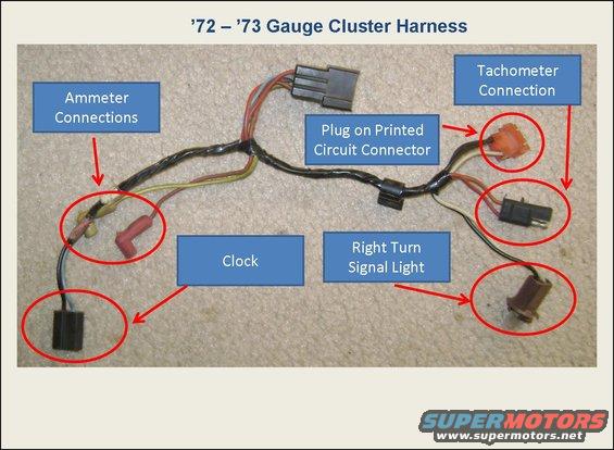
A success update here and the introduction of the next issue. If you examine the picture I posted where you see the IGNITION SWITCH and SWITCH POSITION diagram, you can see a splice S-801 on the 16 - R - LG circuit. It is this splice that was disconnected. The description of the splice in the document says that it is over by the heater box, and, indeed it is. The resistor wire was simply disconnected from the other two wires. I don't really understand why the splice is way over there kind of on the other side of the car, but that's where the wires all terminate, and that's where they (should have been) all joined together. A wire nut solved this issue, and now the proper resistor wire is carrying the voltage to the firewall block, and then on to the MSD voltage hop-up I have so that the MSD coil and distributor is receiving the correct amount of voltage and it is working. The next concerning thing is to figure out why it is working because the tachometer is NOT hooked up! If you look at the diagram in this thread : http://forum.grantorinosport.org/info-72-79-gauge-clusters-and-wiring_topic2933.html The tachometer should be hooked to that coil wire on the engine side of the firewall. If the tach isn't hooked up, the circuit should not be complete and no power should be getting to the coil. I need to figure out what happened to those original splices where the tach should be connected. My intention is to find where that should be on the engine side of the firewall and then make sure the tach is working. This splice would be BEFORE my MSD votage hop-up, of course. I may be posting a whole other thread on this topic, because, again if you look at the above thread, the picture of the 74-76 wiring at the back of the tach, which is also part of the little bundle that includes the ammeter and the clock, I can't find where those wires all connect to. It seems as though the entire 6 pin connector is missing. The back of my instrument cluster has all the barrel pins for the tach, clock, and ammeter, but the actual grey connector just isn't there, and I can't seem to locate it under the dash. Quite odd. That actual connector I am referring to is NOT pictured in that wiring picture I mention. In that picture, all 6 wires just disappear off to the left. It would be nice to see that connector, though with the schematic I have I pretty much know what it looks like. It is labeled as connector C-209. |
|
|
|
|
72FordGTS
Admin Group 
GTS.org Admin Joined: 06-September-2005 Location: Ontario, Canada Status: Offline Points: 5846 |
Post Options
Thanks(0)
Quote Reply
Posted: 08-May-2020 at 12:32PM |
|
I am not really sure what you are asking about the tach? However, you are right, the tach needs to be connected to complete the circuit to the coil. However, you can get around this by converting your tach to a voltage sensing tach. That's what I did so I could run a full 12 volts to the coil and not worry about frying the tach (which needs the resistor wire).
Rocketman converted my tach - top notch work. |
|
|
Vince
1972 Ford GTS Sportsroof - Survivor, One Family car GTS.org Admin |
|
|
|
|
californiajohnny
Moderator Group
Joined: 05-October-2013 Location: winlock, wa Status: Offline Points: 14609 |
Post Options
Thanks(0)
Quote Reply
Posted: 08-May-2020 at 1:13PM |
|
do you have a sport cluster harness? there's a smaller harness that connects that and runs out through the firewall on the drivers side of the brake booster and connects to the engine side harness but you can tap into the coil feed just outside the firewall like shown in the diagram cut and run each end of the cut but to the tach
 |
|
|
JOHN
74 GRAN TORINO S&H CLONE 74 VETTE CUSTOM 90 S10 BLAZER 4X4 LIFTED 77 CELICA CUSTOM 75 V8 MONZA SUPERCHARGED 79 COURIER VERT. SLAMMED 75 VEGA V6 5 SPD 70 CHEV C10 P/U 68 MUSTANG FB CONVERSION |
|
|
|
|
squarethumps
Member
Joined: 30-August-2015 Location: Hunker Pa Status: Offline Points: 112 |
Post Options
Thanks(0)
Quote Reply
Posted: 11-May-2020 at 9:39AM |
|
Here are some pictures for reference. I _think_ it is the "sport" configuration of the instrument cluster ?
Note in this first image that the tach, ammeter and clock, all have the appropriate "pins" there. However, the pins have all been pulled out of the connector. The connector, according to the schematic I have is labeled as C-209. ( Note the picture of the schematic with the Tachometer and the C-209 connector. ) I can not seem to find that connector under the dash. It MUST be under the dash on the inside of the firewall, but I can neither find that connector, nor the place where all those wires go through the firewall nor the splices on the engine side of the firewall, but to be truthful I'm not 100% sure what I should be looking at this point on the engine side. It's just really odd to me that I can not find that connector anywhere. From the images you see that the C-806 connector is there on the back of my tach. I didn't upload an image of that connector, but it is the 2 wire connector. Similarly the schematics of the clock and ammeter also show the proper connectors which you see in the photo of the back of the instrument cluster, and all have the common connector C-209. I am studying all of these schematics and what I see on the car, and again at this point, I don't see how the coil could be getting power without the tach connected. The only conclusion is that the splice(s) that is on the engine side of the firewall which go to each side of the tach, were removed and just joined together to make a continuous wire directly to the coil ( ignoring my voltage hop-up as part of this discussion ).      Edited by squarethumps - 11-May-2020 at 2:03PM |
|
|
|
|
72FordGTS
Admin Group
GTS.org Admin Joined: 06-September-2005 Location: Ontario, Canada Status: Offline Points: 5846 |
Post Options
Thanks(0)
Quote Reply
Posted: 11-May-2020 at 2:25PM |
|
Okay, I think I see what you are trying to figure out now. From the pics you posted, you are missing the connector. This connector should be behind the cluster, and you have to disconnect it when it is removed. I agree, it looks like someone took all the pins out of yours removing the actual connector. Here is a pic of the harness and connector:
 We have more pics and info here in this thread: As your the tach, it sounds like someone may have bypassed yours. The two wire tach needs to be connected for the coil to work, if it hasn't been bypassed. Like I said, though, don't run a full 12 volts through that tach. What year is your car? that would help as there are wiring changes over the years. |
|
|
Vince
1972 Ford GTS Sportsroof - Survivor, One Family car GTS.org Admin |
|
|
|
|
squarethumps
Member
Joined: 30-August-2015 Location: Hunker Pa Status: Offline Points: 112 |
Post Options
Thanks(0)
Quote Reply
Posted: 11-May-2020 at 2:37PM |
|
It is a 1976 (sorry I thought that was in the very first post).
That thread you cited is a great source of information. I've looked at it numerous times for information. The picture you cited is the '72-'73 (or it is labeled as such), and the picture in that same post for the 1976 (posted below) doesn't seem to have the other end of the harness pictured, and it doesn't seem to have any other wires like the '72-'73 for the plug on the printed circuit connector, or the right turn signal light ( odd for that to be grouped with the tach/amps/clock ? ).  I did thing that _PERHAPS_ this was the harness I needed (no years is labeled ), albeit the "other" side of the connector that seems to be missing from mine, but I can't find anything that resembles it on the car currently, and more than that I can't even seem to find the hole in the firewall where it would go ?  Edited by squarethumps - 11-May-2020 at 2:48PM |
|
|
|
|
72FordGTS
Admin Group
GTS.org Admin Joined: 06-September-2005 Location: Ontario, Canada Status: Offline Points: 5846 |
Post Options
Thanks(0)
Quote Reply
Posted: 11-May-2020 at 2:46PM |
|
I am not overly familiar with the later cars wiring. There is a pic of that thread that shows your connector though. Look at the 74-76 cluster in this pic:
 That other harness you posted looks to be the right one IIRC. It comes through the firewall near the brake booster. See it in this pic below of my car but it is a 72.  Edited by 72FordGTS - 11-May-2020 at 2:51PM |
|
|
Vince
1972 Ford GTS Sportsroof - Survivor, One Family car GTS.org Admin |
|
|
|
|
squarethumps
Member
Joined: 30-August-2015 Location: Hunker Pa Status: Offline Points: 112 |
Post Options
Thanks(0)
Quote Reply
Posted: 11-May-2020 at 3:00PM |
|
Wow I never noticed that black connector there in that picture of the back of the 74-76 cluster. It's hard to tell from the picture what is on the other side of that 6 pin connector. It looks like it was cut on the other side. But I do see it there. Another odd thing is that my schematic says that it is a grey connector and that one appears to be black. Nonetheless, that does seem to be the connector I'm missing. Unfortunately, it also seems that I'm missing the other side of that connector and all the wires / plugs that go through the firewall and splice into the other side of the coil wire.
Edited by squarethumps - 11-May-2020 at 3:17PM |
|
|
|
|
squarethumps
Member
Joined: 30-August-2015 Location: Hunker Pa Status: Offline Points: 112 |
Post Options
Thanks(0)
Quote Reply
Posted: 11-May-2020 at 3:17PM |
Just so I am 100% clear, you are referring to the connector / firewall plug that, in the picture is leftmost in the picture, but when describing it on the car, one would say that it is more towards the passenger side of the vehicle. It is "closer" to where the brake booster mounts than the other firewall plug that we see in the picture of your '72, which is closer to the drivers side fender. Is that correct ? On my car, there doesn't even seem to be a hole in the firewall for a plug / harness to go there, so I'm really lost now. LOL |
|
|
|
|
californiajohnny
Moderator Group
Joined: 05-October-2013 Location: winlock, wa Status: Offline Points: 14609 |
Post Options
Thanks(0)
Quote Reply
Posted: 11-May-2020 at 3:23PM |
|
was your car originally a sport cluster harness car, or are you converting to sport?
|
|
|
JOHN
74 GRAN TORINO S&H CLONE 74 VETTE CUSTOM 90 S10 BLAZER 4X4 LIFTED 77 CELICA CUSTOM 75 V8 MONZA SUPERCHARGED 79 COURIER VERT. SLAMMED 75 VEGA V6 5 SPD 70 CHEV C10 P/U 68 MUSTANG FB CONVERSION |
|
|
|
|
squarethumps
Member
Joined: 30-August-2015 Location: Hunker Pa Status: Offline Points: 112 |
Post Options
Thanks(0)
Quote Reply
Posted: 11-May-2020 at 4:55PM |
I am not sure what it originally was as far as the cluster goes. I know it's a 1976 #0022 S&H car. I have a Marti, but it doesn't say anything about the gauges. I acquired the car and the dash was already put together and it looked rather original, with the exception of a new dash "top". I have pictures of the body work that was done to the car, which includes floor pans and a repair of one of the door hinge posts, but nothing pictured that shows any kind of repair / replacement of the firewall. It's been about 4 years since I took apart the dash to figure out what was going on with the lack of power to the coil. I got sidetracked with other matters. I don't remember removing all of those pins from the connector when I removed the instrument cluster, and I'm inclined to believe that if I was taking out the gauge cluster and going to disconnect a harness, I wouldn't have had reason to remove all of those pins from their connector. I also don't really recall the tachometer working when I did get the car running originally but I think it was because we wired hot directly to the coil just to get the engine running. All that to say .. I'm not sure I guess, but the placement of the wires in their hold downs( clips and wire ties and such ) and the "crispyness" of the tape that was on the harness when it removed it for examination and repair, makes me to think that it was all original. |
|
|
|
|
squarethumps
Member
Joined: 30-August-2015 Location: Hunker Pa Status: Offline Points: 112 |
Post Options
Thanks(0)
Quote Reply
Posted: 12-May-2020 at 1:46AM |
You know .. the more I look at that picture the more I think that the wires / firewall hole and plug you are talking about is actually to the "right" of the brake booster, that is, on the passenger side of the brake booster ? That looks to me like there are more of and the same color wires that I'm looking for ? Maybe that's where I'm making my mistake. I'll have to check later today. |
|
|
|
|
72FordGTS
Admin Group
GTS.org Admin Joined: 06-September-2005 Location: Ontario, Canada Status: Offline Points: 5846 |
Post Options
Thanks(0)
Quote Reply
Posted: 12-May-2020 at 12:36PM |
|
That plug comes through on the driver's/left side of the booster. This is a '72, so they may have changed things by '76. It says in the description on your diagram "Engine compartment/LH side of dash". So it doesn't really narrow it down under the hood.
Maybe John has a good pic of his firewall on his car? His is a '74 so it should be similar to yours. I am wondering if your car maybe didn't have the sport cluster originally? Was it listed on your Marti Report? Also BackinBlack just post a '74 to 76 style cluster for sale. He has a good pic of the back of his:  |
|
|
Vince
1972 Ford GTS Sportsroof - Survivor, One Family car GTS.org Admin |
|
|
|
|
squarethumps
Member
Joined: 30-August-2015 Location: Hunker Pa Status: Offline Points: 112 |
Post Options
Thanks(0)
Quote Reply
Posted: 13-May-2020 at 3:52AM |
So first I was not clear that the gauge cluster I have is a sport cluster. I am gathering that it IS a sport cluster is that correct ? Secondly, I don't see anything at all about a "cluster" or instrument panel or anything relevant to the dash, or sport model mentioned in either the regular Marti report I have or the "Deluxe Report" that I have. It says that it is a Gran Torino 2-Door Hardtop built March 18th 1976, so an early '76 Torino. However, what I do notice is that the car originally came with Black Vinyl Bench seats, but when I acquired the car it has black / red stripe bucket seats. I wonder did the guy totally acquire a Gran Torino Sport interior and then put it into this car, and that's why I have this instrument cluster ? Again though, it just seems like the wiring and dash are all original to me ?  Edited by squarethumps - 13-May-2020 at 2:44PM |
|
|
|
|
californiajohnny
Moderator Group
Joined: 05-October-2013 Location: winlock, wa Status: Offline Points: 14609 |
Post Options
Thanks(0)
Quote Reply
Posted: 13-May-2020 at 4:53PM |
|
ok, mine was a std cluster... i converted it! not sure if the std cars even had the hole for the short extra harness i'll look for a good pic...
far as i know PS122 cars didn't come with sport clusters???( but i could be wrong? yes that red/lack interior is from the 74 sport there were 3 color options...black/red, tan/orange, and blue/lt blue idk if it specifically states on a marti about the cluster??? maybe someone else can chime in on that... a couple sport cluster cars i parted had that hole for the short harness on the drivers side of the booster between it and the main harness bulk head here's a pic of my firewall... no it does not have that hole! mine was a standard cluster car originally. i didn't buy the short harness... i wired it up myself instead  |
|
|
JOHN
74 GRAN TORINO S&H CLONE 74 VETTE CUSTOM 90 S10 BLAZER 4X4 LIFTED 77 CELICA CUSTOM 75 V8 MONZA SUPERCHARGED 79 COURIER VERT. SLAMMED 75 VEGA V6 5 SPD 70 CHEV C10 P/U 68 MUSTANG FB CONVERSION |
|
|
|
|
californiajohnny
Moderator Group
Joined: 05-October-2013 Location: winlock, wa Status: Offline Points: 14609 |
Post Options
Thanks(0)
Quote Reply
Posted: 13-May-2020 at 4:58PM |
|
the speedo hole is to the right of the booster and below that is the column shift cable hole if you have a floor shift they may have put that connector plug out though it??? but idk if it would reach to plug in to the main harness? but who know what other people do and why
 |
|
|
JOHN
74 GRAN TORINO S&H CLONE 74 VETTE CUSTOM 90 S10 BLAZER 4X4 LIFTED 77 CELICA CUSTOM 75 V8 MONZA SUPERCHARGED 79 COURIER VERT. SLAMMED 75 VEGA V6 5 SPD 70 CHEV C10 P/U 68 MUSTANG FB CONVERSION |
|
|
|
|
72FordGTS
Admin Group
GTS.org Admin Joined: 06-September-2005 Location: Ontario, Canada Status: Offline Points: 5846 |
Post Options
Thanks(0)
Quote Reply
Posted: 14-May-2020 at 6:01AM |
|
Since the gauge package/sport cluster was an option, it would be listed on the Marti report if your car had it. IIRC, some of the later GTS cars, 74-75 had the gauges as a standard feature, but the '72-73 didn't and off the top of my head, I don't think any 1976 Torino came with them standard either as teh GTS was gone in 1976.
So based on what John posted I think your car probably didn't have a gauge package from the factory and someone tried to retrofit it. That's probably why both your car and John's don't have the hole in the firewall like mine. At this point, you might be better off to just wire it up on your own, without the harness, unless you are trying to make it factory correct. Anyone on here have a '74 to '76 Torino with the gauge package option from the factory? Maybe they can post a pic of the firewall too so we can confirm this info.
Edited by 72FordGTS - 14-May-2020 at 6:10AM |
|
|
Vince
1972 Ford GTS Sportsroof - Survivor, One Family car GTS.org Admin |
|
|
|
|
squarethumps
Member
Joined: 30-August-2015 Location: Hunker Pa Status: Offline Points: 112 |
Post Options
Thanks(0)
Quote Reply
Posted: 14-May-2020 at 6:07AM |
|
So my firewall has the 2 holes to the right of the booster (towards the passenger side). The one closest to the booster has the spedo cable which goes to the transmission. The next one is the throttle cable. There are no other holes in the firewall.
My car has a floor shifter. Again it seems to be original, but does it seem correct that the car would come originally with a bench seat AND a floor shifter for an automatic transmission ( C-6 )? That seems like something that they wouldn't have done. Would it help if I posted the Marti Reports ? Is there any danger in that ? The Marti report says that the car was ordered with a tilt steering column. The column that is in the car now does not appear to be a tilt style. I can't find where the "tilting" mechanism is. I mention all of this as part of the process of trying to figure out what is original on this car, and what has been changed out. The pictures I have of the body work just show the floor pans like I said but the "hump" in the middle seems to be original, and more than that there is a center console with the proper supports in between the bucket seats now. The screw holes for that must have been drilled / tapped after the bench seat was removed ? I'll pull up the carpet and take some pictures and maybe someone has an opinion on what is original or swapped. |
|
|
|
|
squarethumps
Member
Joined: 30-August-2015 Location: Hunker Pa Status: Offline Points: 112 |
Post Options
Thanks(0)
Quote Reply
Posted: 14-May-2020 at 6:16AM |
Well, with all of those pins there on the back of my sport cluster, yes I would like to just be able to plug those into an original type connector and then have the wiring correct with the factory diagrams. A further concern I have is that if the wiring under the dash is original, but the instrument cluster is not, is there going to be issues with the main cluster connector ? Like, how different is the original wiring harness in the non-sport, vs the sport models, that might cause issues with the pins which basically connect to the cluster's printed green ribbon ? Or should that be fine and that is why these optional gauges ( tachometer, clock and ammeter ) are basically in a separate harness ? With respect to the non-sport cluster. I suppose then that the non-sport cluster did NOT have a tachometer at all ? I found this : but the colors of the wires for the tach are not perfectly matching with my diagrams so I would just remove the pins from that connector and put in my own. According to the picture I posted above with the C-209 connector, that is part of harness 10817 on the "other side" and the harness you see in the picture below is 10B942.  10B942 for sale <SOO MUCH TO LEARN LOL> Edited by squarethumps - 14-May-2020 at 6:49AM |
|
|
|
|
californiajohnny
Moderator Group
Joined: 05-October-2013 Location: winlock, wa Status: Offline Points: 14609 |
Post Options
Thanks(0)
Quote Reply
Posted: 14-May-2020 at 2:34PM |
|
the main connector will fit i had to swap positions of 3??? wires in the connector unfortunately it was several years ago and i don't recall which ones??? i think it was the gas oil and water sending wires??? i took my std cluster and the sport and traced down each circuit on the board to the connector end and made notes then seen most were in the same location except those few, removed them from the connector and plugged them back into the new positions
my brain works like a schematic but trying to explain that to someone can be impossible for me sometimes keep in mind the gauges that share a common connection to 1 pin will be the positive power side of the gauge the other side will have it's own separate pin will be the negative to that individual sender now on the turn lights and high beam those that share a pin will be the ground, each individual pin to that bulb will be the positive to it the dash bulbs will have a common ground pin location and common pin location for the power to them which is the light blue with a red stripe wire it should be in the same location on the main connector i believe so this may help to track down a few by process of elimination |
|
|
JOHN
74 GRAN TORINO S&H CLONE 74 VETTE CUSTOM 90 S10 BLAZER 4X4 LIFTED 77 CELICA CUSTOM 75 V8 MONZA SUPERCHARGED 79 COURIER VERT. SLAMMED 75 VEGA V6 5 SPD 70 CHEV C10 P/U 68 MUSTANG FB CONVERSION |
|
|
|
|
squarethumps
Member
Joined: 30-August-2015 Location: Hunker Pa Status: Offline Points: 112 |
Post Options
Thanks(0)
Quote Reply
Posted: 15-May-2020 at 5:30AM |
@californiajohnny this is most distressing lol. I guess the light at the end of the tunnel is that I have the schematic I have and it seems like all the colors of the wires that it calls for are correct. So at least the wiring that is there is a "known". Then I can start to label out the pins on the sport cluster I have and compare that with the original wires and the connector that is there and see what needs to change. That is very good information you gave me about the shared positive and negative. I tried using a voltmeter and the continuity indicator ( the tone ) a couple years ago to try and see what was what, but with circuits like that, there's always some connectivity. It was trying to hear the difference between a loud buzz and a quiet buzz, and then try and interpret that meaning. Rather painful. That was before I got the schematic though. I need to get all the pages in that schematic copied and laminated or even scanned into a coherent digital format. |
|
|
|
|
squarethumps
Member
Joined: 30-August-2015 Location: Hunker Pa Status: Offline Points: 112 |
Post Options
Thanks(0)
Quote Reply
Posted: 15-May-2020 at 5:41AM |
|
So .... All:
I'm now looking for that connector that I'm missing from the 10B942 harness ( of which I have all BUT that connector ), AND I'm looking for the entire 10817 harness that goes through the firewall. I guess I will drill the correct size hole through the firewall to install everything properly. Of course I will only do that once I'm 100% sure that I have everything mapped out. Anyway .. does anyone have any of those connectors / harnesses ? <yinz have been quite helpful up to this point, thank you all so much> |
|
|
|
|
Post Reply
|
Page 123 5> |
| Tweet |
| Forum Jump | Forum Permissions You cannot post new topics in this forum You cannot reply to topics in this forum You cannot delete your posts in this forum You cannot edit your posts in this forum You cannot create polls in this forum You cannot vote in polls in this forum |


 Topic Options
 squarethumps wrote: